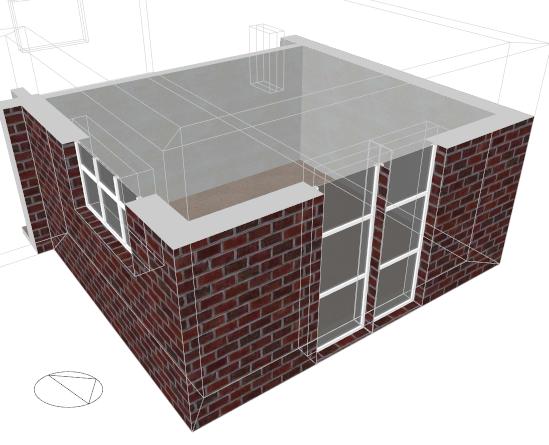
Cutaway of DesignBuilder Zone showing 3D-slabs
The meaning of most surface types listed in the Navigator should be obvious. This section provides further information on the meaning of 3 less obvious surface types:
These special surfaces are required because DesignBuilder uses 3-D surface slabs to represent building fabric. Using 3-D surface slabs allows accurate calculation of zone volumes, definition of blocks using external dimensions and realistic rendered images. Zones for EnergyPlus simulations and other calculations provided by DesignBuilder are generated from the interior faces of the block geometry.
Cutaway of DesignBuilder Zone showing 3D-slabs
An Inter-block partition surface is the shared partition wall between 2 zones in different blocks. Inter-block partition surfaces are generated whenever 2 blocks touch along a plane. They are listed in the Navigator twice, once in each of the 2 zones in which they appear. They are however a single partition object within DesignBuilder and in the thermal calculations. So if, for example, you change the Partition construction model data for an inter-block partition (or draw windows) the change will also be reflected in the equivalent inter-block partition surface in the adjacent zone.
Surfaces marked Wall (with hole) in the navigator are external surfaces on the same block face as an inter-block partition surface (see above). The 'hole' is where the inter-block partition goes. So 'Wall (with hole)' is the part of the block face that is adjacent to outside. The partition with the adjacent block is in a separate surface called inter-block partition (it is separated from the rest of the wall because it has a different adjacency). So the sum of the inter-block partition(s) and the wall with the hole make up the actual surface. The figures below illustrate.
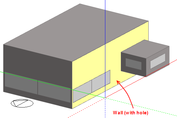
At building level
At surface level
Note that at surface level you can only draw openings on the grey areas of the surface. The white 'hole' is actually the inter-block partition (above).
Because EnergyPlus does not allow surfaces to be defined with holes (i.e. surfaces are defined using a single set of vertices) DesignBuilder generates 2 or more valid sub-polygons to represent the surface in EnergyPlus. The diagram below illustrates the procedure used for a typical Wall (with hole) surface.
 polygons.png)
The surface is split into 2 (often equal area) polygons that, together, enclose the 'hole' left by the interblock partition. You should bear this in mind when looking at EnergyPlus IDF data.
Link body edge surfaces are used to connect the Wall (with hole) and the Inter-block partition surfaces to ensure that zones are fully enclosed. They are required because zones in adjacent blocks are separated from each other due to the thickness of the walls of the 2 blocks. The link body edge surfaces bridge the gap between the (internal) zone shell and the (external) block shell. The link body is the volume between the link edge surfaces and the inter-block partition.
Link body edge surfaces are excluded from the calculations by default to keep the size of models down but you can change the setting under Miscellaneous Edit on the Advanced tab of the Model options dialog to include them. When included, these surfaces are modelled using very high resistance zero mass elements and their contribution is to:
The pictures below show how the link body edge surfaces are used to connect the 2 blocks and ensure that zones are enclosed.
EnergyPlus Model with link body edge surfaces - zones are enclosed and the zone volume
includes the volume enclosed by the link surfaces and the inter-block partition. This volume is
the thickness of the block wall x inter-block partition area).
Equivalent EnergyPlus Model without Link body edge surfaces - zones are not enclosed and
the zone volume excludes the link body (volume enclosed by the link surfaces and the inter-block partition).