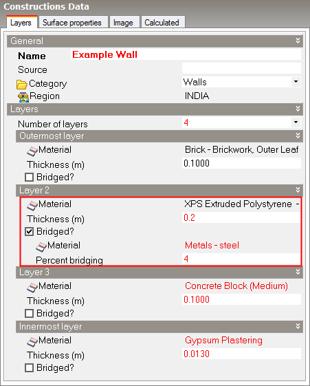
Layers tab on Constructions Dialog.
Set the number of layers first, then select the material and thickness for each layer. Use the Controls in the Info Panel to insert and delete layers. For example to delete a layer, first click on the material for the layer to identify which layer you want to delete, then click on Delete layer.
You can create constructions with up to 6 layers.
You should define the layers in the same order they appear in the actual construction starting with the outermost layer and finishing with the innermost. The outermost layer will be positioned adjacent to outside (or in the case of Semi--exposed walls) adjacent to the semi-exposed unconditioned zone.
For interior surfaces (partitions, internal floors etc) the order of the layers is determined through a series of checks to see which zone is relatively ‘more external’. For example, if one zone is unconditioned and the other not then the partition layers are ordered so that the outermost layer is next to the unconditioned zone. When both zones are occupied, a similar check is made using heating and cooling setpoint temperatures. If after all these checks the zones are still both equally ‘internal’ then the direction of the layers will be set up in an arbitrary way.
Note: You should not include surface resistance (film coefficient) layers to represent the resistance of the air films adjacent to the inner and outer surfaces. These are included automatically by DesignBuilder.
This field characterizes the thickness of the material layer. This is the dimension of the layer in the direction perpendicular to the main path of heat conduction. This value must be a positive.
Note: If the material referenced is defined as a simple R-value then the construction thickness does not have to be entered.
You can add repeating thermal bridging to any layer to model the effect of a relatively more conductive material bridging a less conductive material. For example wooden joists bridging an insulation layer.
Note: bridging effects are not yet used directly in EnergyPlus, but are used in energy code compliance checks requiring U-values to be calculated according to BS EN ISO 6946. However see below for a workaround to this limitation.
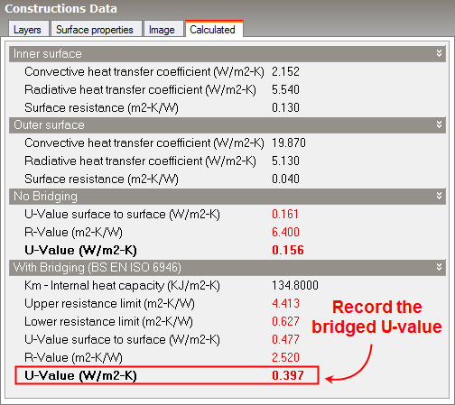
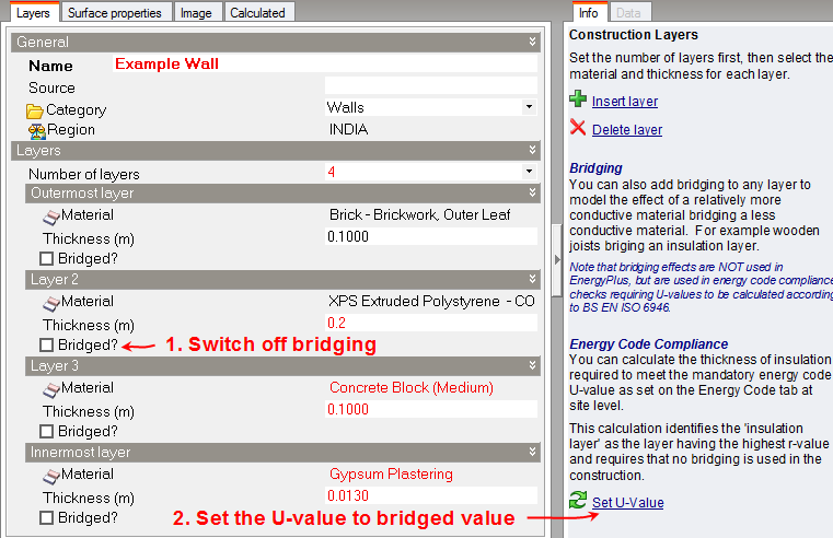
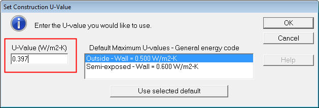
Although EnergyPlus cannot allow repeating bridging directly in simulations it is possible to approximate the effect of bridging by adjusting the thickness of the insulation to a value that gives the same U-value as the bridged construction calculated using BS EN ISO 6946. This is easily achieved by following these steps: