Openings tab in model data under External Glazing and Internal Glazing headers
You can use the Window to wall % (WWR) data and Window height, Window spacing and Sill height to easily change the amount of glazing and its layout on the walls. The way this data is used for each facade type is described below.
There are a number of standard facade types:
Often referred to as the Window to Wall Ratio (WWR) this data can be used to change the amount of glazing for all openings at or below the current level in the building hierarchy. For example changing the WWR at building level changes the size of all windows in the model not overridden by other settings lower in the hierarchy.
The spacing between the each window on the facade (in m or ft). The window spacing is the centre to centre spacing between windows, not the gap between windows.
This is the height of the base of the window from the base of the block (in m).
Note 1: You can control the makeup of the building facades in greater detail by drawing individual windows at the surface level or by copying previously drawn windows at building level. In either of these cases glazing, vent and door facade layout model data is ignored.
Note 2: Flat roofs do not have default glazing set up using Roof glazing layout model data. To create openings on a flat roof you should go to the surface level and add them there.
Note 3: Even with the 2 Facade type options that prioritise Window to wall % (3-Preferred height and 1-Continuous horizontal), when the surface is non-rectangular, the Window to wall % will not be perfectly maintained. For these surfaces, DesignBuilder calculates a rectangle that can accept the windows and starts from one end of the rectangle adding windows using the Window spacing data until no more fit into the rectangle. This results in an approximately correct looking facade but only prioritises Window to wall % in the rectangle, not accounting for the areas outside the bounding rectangle. For relatively large values of Window spacing on non-rectangular surfaces, no glazing may be generated. For example you may find that gable window surfaces have no default windows generated and it is often easiest to draw a window in this case.
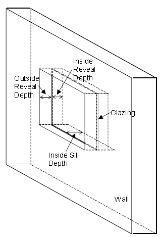
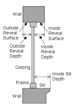
The schematics below show how DesignBuilder reveal data is used to describe real glazing systems.
Although it is possible for inside reveal depth to be calculated from the outside reveal depth and the block wall thickness, DesignBuilder allows both Inside and Outside reveal depths to be defined gives greater flexibility for situations where it is not possible to enter the block wall thickness as accurately as one might like. For example in some cases there might be a variable wall thickness in the building design but DesignBuilder requires a single value per block, so the block wall thickness might not be 100% accurately defined in the model. Being able to enter the reveal depths gets round this problem. Also some users may enter Block wall thickness as the lowest allowed value (0.01m) so as to be able to enter interior room dimensions when defining blocks instead of the more usual exterior dimensions. In such cases having direct control over the reveal depth data is an advantage.
The outside reveal depth gives the extent to which the glazing is offset into the wall. As shown in the above diagram it is the distance from the exterior surface of the wall to the glazing outer surface (in m or ft).
Note: EnergyPlus models outside reveals through the co-ordinates of the window, which are offset into the zone so the window and the base surface don't lie on the same plane. DesignBuilder provides window co-ordinates to EnergyPlus in this way and there is no specific data item in the IDF data to define it.
Note: In DesignBuilder v3.0 the outside reveal depth is used in EnergyPlus only. In Visualisations and Daylighting calculations the window is assumed to be positioned halfway between inside and outside surfaces.
The inside reveal depth is the distance (in m or ft) from the innermost surface of the window to the interior wall surface as shown in the diagram above.
The inside sill depth is the distance (in m or ft) from the innermost surface of the window to the innermost end of the sill as shown in the diagram above.
The "FenestrationSurface:Detailed" window data written to the EnergyPlus IDF input file will usually have a slightly smaller area to the area defined in DesignBuilder. This is to account for the frame which is included in the window area defined in DesignBuilder but excluded from the IDF window area. In cases where the frame option is switched off in DesignBuilder the frame area in the IDF data will match the area set in DesignBuilder.