In EnergyPlus, heat is transferred between zones and the ground through one-dimensional ground floor surface elements. The 2-D and 3-D effects in the ground heat conduction that occur in reality are not treated by default. EnergyPlus uses ground construction data to model the storage of heat in the ground and it can accurately model heat transfer processes over several days (so it can model the effect of say a warm week followed by a cool week) but it cannot directly model long-term ground thermal storage effects (periods measured in months). For more on advanced ground modelling see bottom of this topic.
EnergyPlus applies a constant temperature boundary condition for each month on the lower surfaces of ground adjacent elements.
There are 3 ways to create an adjacency to ground in DesignBuilder:
When using Separate constructions, and when the Add ground construction layers to surfaces in contact with ground option is selected, DesignBuilder automatically combines the site ground construction (0.5m of earth by default) with the main construction (typically ground floor or wall) set on the Constructions tab. With Combined constructions the earth layers must be explicitly included in the ground floor/wall constructions if you wish to define ground temperatures within the earth.
Monthly ground temperatures are defined at the site level under Site details.
Note: You should not use the ground temperatures in the EnergyPlus weather file header because these are for undisturbed sites. The temperature beneath buildings is significantly affected by the building itself - the EnergyPlus documentation recommends using ground temperatures of 2°C below average internal temperatures for large commercial buildings (where perimeter heat loss is relatively less important). Note that this temperature should be applied directly below the slab and should not include ground material - so if you use this approach to ground temperature definition, you should switch off use of the ground construction at the site level.
EnergyPlus cannot model very thick constructions so it is necessary to use less thick constructions (2m or smaller) combined with some assumptions about temperatures at about half a metre below the floor.
Many modellers prefer to define the ground temperature just below the slab and exclude the earth layers from the model. This has the advantage of simplicity and clarity and is the approach recommended by EnergyPlus developers.
Note: the default ground temperatures provided in DesignBuilder assume that an earth layer is included in the constructions adjacent to ground. If an earth layer is not included then you should increase the default site ground temperatures to values closer to those typically found just below the ground slab (as described in note above).
This example illustrates how to create a simple 3 storey rectangular building model with:
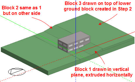
Draw 3 blocks on the z=0 ground plane. The lowest block will be the basement (completely buried), the middle block will be the ground level block, partially buried and the top block will be the second level. So far only the bottom surface is adjacent to ground because it sits on the z=0 plane.
Draw 2 ground component blocks around the basement building block to give it's surfaces ground adjacency.
Note this step could be avoided by moving the whole building down so that the basement is fully below ground. To do this go to building level, select all the blocks, select the move command, click on one of the bottom corners of the middle block to create a reference point then click on a blank part of the screen to move the reference point down to z=0.
Draw three new ground component blocks to create the sloping ground and the upper ground levels.
The zone of the middle block is shown above. Notice how 3 of the surfaces have been split into external and ground adjacencies (ground adjacencies are flagged by green ground symbols). Note also that the portions of the surfaces touching the ground component block cannot have windows but DesignBuilder attempts to set up the correct % glazing for the remaining external parts of the surface.
The ground component blocks probably do not need to shade this model as they are mainly below all surfaces that can receive solar radiation/light, but if you are modelling reflections you will probably need to include the reflection of solar radiation and light from the ground blocks during simulations. In other cases you may prefer to switch off the generation of the component blocks shading/reflection surfaces to speed simulations. Do this on the Constructions model data tab under Component Block.
The finished model. The texture of Ground component blocks is defined by the material set under Component blocks on the Constructions tab.
To accurately model long-term ground thermal storage you may wish to consider using an external 2 or 3-D conduction tool such as the ‘Slab’ utility supplied with EnergyPlus. This can be used to calculate the temperatures applied to the underside of the ground floor surface elements.
The EnergyPlus slab program produces temperature profiles for the outside surface at the core and at the perimeter of the slab. It also produces the average based on the perimeter and core areas used in the calculation. EnergyPlus has a single GroundTemperatures object that is used for twelve monthly average ground temperature values - see the Input Output Reference document. Because of this, there are two options for dealing with the ground temperatures:
Detailed ground modelling may only give a marginal difference in results and you might want to carry out a sensitivity study to check the influence of ground temperatures on simulation results before deciding on the most appropriate level of detail.
DesignBuilder version 2 does not account for 2-D and 3-D thermal bridging effects but future versions may.