Radiance illuminance daylighting calculations are based on a single static sky distribution and are controlled using a set of options on the Daylighting calculation options dialog which is displayed before the calculations are started. It is important to make selections consistent with the purpose of the analysis and nature of the building model.
Select the type of report that you will require after the calculations have finished. Options are:
If you do not require any particular report then select 1-General.
Note: Daylight results are stored separately for each Simulation type so you can generate and store multiple results sets, one for each of he above, each potentially using different calculation option settings.
Select a detail template from the drop list to load a set of ambient parameters to the dialog as shown in the table below.
You do not necessarily need to have an in-depth understanding of the meaning of each of these parameters to carry out an accurate assessment in DesignBuilder. However knowing a little bit about the way the calculations work and how the options affect the calculations will help you to understand how to get the best trade-off between accuracy and simulation times.
It is important to understand that Radiance works using a statistical Monte Carlo approach and this means that you will not get exactly the same results if you repeat a calculation using exactly the same model and options. You can reduce this effect by using higher detail settings but you cannot completely eliminate it. This is discussed in more detail under Advanced options below.
| Detail template | |||||
|---|---|---|---|---|---|
| Radiance code | -ab | -aa | -ar | -ad | -as |
|
1-Fast Not recommended for project work |
1 | 0.3 | 128 | 256 | 128 |
|
2-Standard Default setting, but will underestimate illuminance |
3 | 0.25 | 256 | 512 | 256 |
|
3-Good (no interpolation) |
4 | 0.00 | 512 | 1024 | 512 |
|
4-Good |
4 | 0.22 | 512 | 1024 | 512 |
|
5-Accurate Best setting for highest practical accuracy |
5 | 0.20 | 512 | 2048 | 1024 |
|
6-High quality Use when highest quality is required and a long wait for results is acceptable |
7 | 0.18 | 1024 | 4096 | 2048 |
Tip: For a discussion on the relative merits of using some of the above settings for daylight credit calculations see below.
Enter the height of the working plane above floor level for each zone in the daylight simulation (in m or ft). The default value will depend on the Report type selected. The working plane height entered on this dialog corresponds with the building level setting on the Output model data tab.
The working plane height is normally set at the average height of the top surface of the desks above the floor. A typical value will be in the range 0.7-0.8m.
Note: The working plane height used in Radiance calculations is measured from the top of the floor surface level, not the base of block as was the case in v5.0 and earlier.
Tip: To define different working plane heights for different zones, you can override the building level setting on this dialog by entering values under the Daylighting outputs header on the Outputs model data tab at block or zone level.
Enter the margin (in m or ft) around the zone boundaries where illuminance data is not to be included in summary results. This option can be used to help avoid inclusion of potentially misleading illuminance data close to walls and windows. DesignBuilder sets the default margin depending on the simulation type selected.
If you enter a value greater than zero in this cell, DesignBuilder automatically generates a ground plane below all site objects to model ground-reflected light. The ground plane is generated behind the scenes and its dimensions are calculated by setting up a rectangular box in the plan view around the building extents and adding the Ground plane extension at each edge.
The auto-generated ground plane uses the Ground reflectance defined at site level.
An alternative approach to model ground reflectance is to set the Ground plane extension to zero and to use ground component blocks instead. Or a combination of ground component blocks and the ground plane extension can be used.
Tip: While it may be tempting to enter a very large number here to cover a large area, that is not usually recommended as it would significantly change the scene dimensions used within Radiance. Larger scene dimensions require high detail settings which may require very long simulation times.
There are 2 general methods for generating the sky illuminance distribution for the Radiance calculation:
When the Sky method is set to 2-Perez all weather there are 4 methods to choose from depending on the data you have available. In all cases the time, day and month of the analysis must be set to define the location of the sun in the sky.
3-Direct horizontal irradiance for when measured (or calculated) direct horizontal and diffuse horizontal irradiance data is available. Such data can usually be found in EnergyPlus epw files in W/m2.
Perez sky clearness (ε). Enter a value from 1.0 to 12.0.
Available only when using the 2-Perez all weather Sky method and the 1-Brightness and clearness Perez method
Perez sky brightness (Δ). Enter a value from 0.01 to 0.6.
Available only when using the 2-Perez all weather Sky method and the 1-Brightness and clearness Perez method
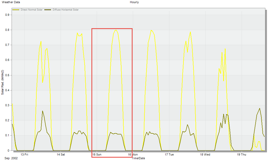
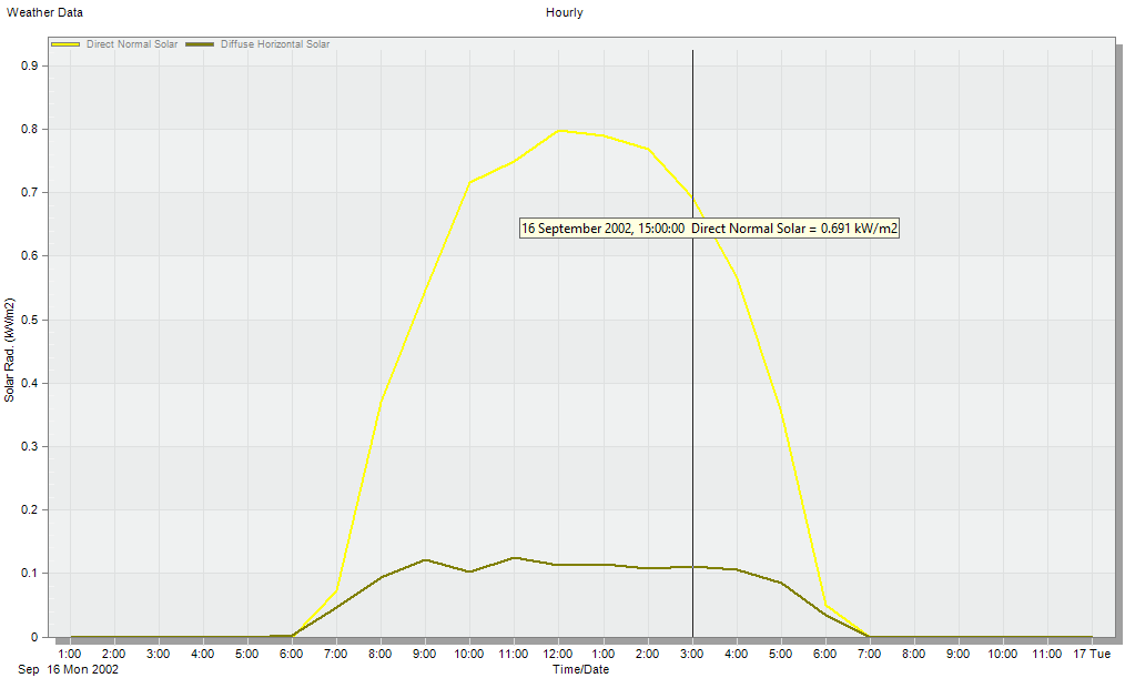
The direct normal solar broad spectrum irradiance (in W/m2 or W/ft2). This value can be found from the site level hourly weather data.
Available only when using the 2-Perez all weather Sky method and the 2-Direct normal irradiance Perez method.
The diffuse horizontal solar broad spectrum irradiance (in W/m2 or W/ft2). This value can be found from the site level hourly weather data.
Available only when using the 2-Perez all weather Sky method and the 2-Direct normal irradiance or 3-Direct horizontal irradiance Perez method have been selected.
The direct normal illuminance (visible spectrum) (in lux or fc).
Available only when using the 2-Perez all weather Sky method and the 4-Direct normal illuminance Perez method
The diffuse horizontal illuminance (visible spectrum) (in lux or fc).
Available only when using the 2-Perez all weather Sky method and the 4-Direct normal illuminance Perez method
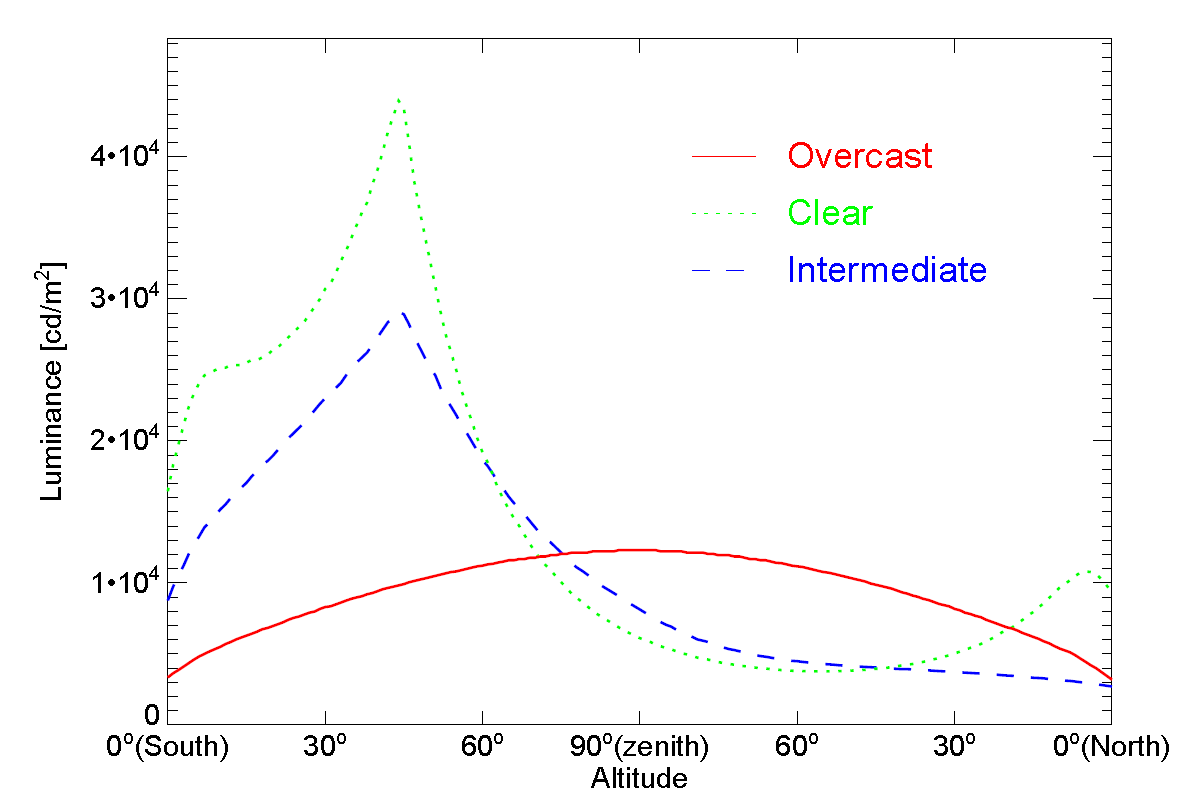
When using the 1-Standard sky Sky method, select the sky model to be used for the daylighting calculations. Select from:
Sky luminance profiles for 3 sky models (Source Rendering with Radiance: A Practical Tool for Global Illumination)
When the Sky model (above) is set to 6-CIE overcast day (scaled) you can define the scaling illuminance at the Zenith (in lux or fc). The default is 10,000 lux which allows daylight factors to be calculated simply as working plane illuminance values divided by 100.
An important part of the LEED v4 Option 2 daylight calculation is to set the sky conditions to be used in the simulations. This must be done using the 2-Perez all weather Sky method. The procedure required for this is described by USGBC:
Calculate illuminance intensity for sun (direct component) and sky (diffuse component) for clear-sky conditions as follows:
Method 1 using Direct horizontal irradiance
Based on LEED documentation:
- Obtain typical meteorological year data. Use local weather data or TMY weather data files for the nearest city.
- To calculate the illuminance intensity for sun (direct component) and sky (diffuse component) in a TMY2 or TMY 3 file, you can export the data into spreadsheet format.
- From the TMY, select the day within 15 days of September 21 that has the clearest sky condition (total sky cover at its lowest value) at 9 A.M.
- From the TMY, select the day within 15 days of March 21 that has the clearest sky condition at 9 A.M.
- Determine the direct horizontal irradiance (W/m2) values at 9 A.M. for the day selected in September and at 9 A.M. for the day selected in March. Average the two values and use the result in the 9 A.M. simulation as the direct horizontal irradiance input. If the file does not explicitly state direct horizontal irradiance, calculate it as follows:
Direct horizontal irradiance = Global horizontal irradiance – Diffuse horizontal irradiance- Determine the diffuse horizontal irradiance (W/m2) values at 9 A.M. for the day selected in September and at 9 A.M. for the day selected in March. Average the two values and use the result in the 9 A.M. simulation as the diffuse horizontal irradiance input.
- Repeat procedures 3–6 for 3 P.M.
- Choose the 2-Perez all weather Sky method.
- Choose the 3-Direct horizontal irradiance Perez method.
- Input the custom values for Direct horizontal irradiance and Diffuse horizontal irradiance in the Calculation options dialog and run the Radiance simulation.
Method 2 using Direct normal irradiance
Another (simpler) procedure to provide the sky condition data within DesignBuilder is as follows:
The main grid size that can be used to divide up the working plane when calculating illuminance. Larger values will speed up calculations but give lower resolution in daylighting outputs.
You should consider the size and number of zones in the building when selecting the grid size. A very fine grid will of course cause Radiance calculations to take a lot longer to complete. On the other hand a very coarse grid in a small zone may not give a good enough distribution.
You should use a maximum grid size no greater than 5ft or 1.5m for LEED EQ8.1 calculations.
This is the smallest grid size that can be used to fill in gaps in the working plane in cases where the maximum grid size is too large, especially at the edges of the plane. Use smaller values (e.g. 0.01m) to fill in most gaps between the main grid cells and the borders of the working plane for a more continuous output. It is common to use a Minimum grid size that is a factor of between 0.5 and 0.1 times the Maximum grid size.
To maintain a uniform grid across the working plane set the Minimum grid size the same value as the Maximum grid size.
DesignBuilder Radiance is ideal for calculating daylighting credits for certification schemes such as LEED, BREEAM and Green Star. In these cases there is often pressure to provide highest possible illuminance reports and, because some settings can cause illuminance values to be lower than expected, this section provides advice on the most appropriate settings to use.
Many of the LEED, BREEAM and Green Star daylighting credit calculations revolve around a "% of floor area having daylight illuminance over a threshold" report for each zone and for the whole building. The table below describes how to get the most accurate results from these calculations.
| Setting | Recommended Setting | Advice |
| Detail template | 5-Accurate | You should use the most detailed setting you can afford to wait for. The 1-Fast setting is not intended for project output and should be avoided for all credit calculations as it tends to lead to severe underestimates of illuminance levels. The accuracy increases as the level of detail in the calculation increases up to and including the 5-Accurate setting. The 6-High quality setting is not recommended for these sort of calculations either as it does not add much in terms of accuracy but takes a lot longer than the 5-Accurate setting. |
| Ambient Bounces | 3-8 |
The 5 built in templates are ideal for “simple daylight scenes that have shallow spaces with relatively large window openings”. However in deep plan models or models with small windows or greater external/internal complexity of the model you may want to increase the number of bounces from the default set by the Detail template. Models which have complex exterior geometry may require up to 8 bounces to ensure that the light reflection from exterior building surfaces is correctly treated. Likewise to obtain the correct impact of variations in the floor reflectance you will need to use 5 or more bounces. Tip: If you aren't sure, try experimenting with different values for this setting to test sensitivity and learn impact on results. |
| Grid size |
Max: 0.2m Min: 0.05m |
Of course, the finer the overall grid the more accurate the results. Perhaps less obvious however is that using lower values for Minimum grid size can lead to more accurate and higher zone average illuminance results. This is because the small grid cells generated with the low minimum grid size can fill in around the edges of the working plane where often the highest levels of daylight are to be found. |
| Margin | 0 | Use a zero margin if you need the entire working plane to be included in the results. This will often lead to higher % areas over daylight thresholds because the edges of the working plane are usually closest to where many of the windows are located. |
The following options are available on the Daylight Calculation Options Dialog for static illuminance and annual CBDM simulations. They govern the quality of the simulation and are best set through the Detail template by non-expert users.
The number of ambient bounces is the maximum number of diffuse bounces computed by the indirect calculation. The number of ambient bounces that Radiance should apply varies depending on the type of building and daylighting system you are analysing. It can be set based on the number of reflections typically required by the light to reach the task plus one or two extra for inter reflection within the space.
The number of bounces should normally be set to 3 for most accurate calculations or 2 if some trade-off is acceptable. 4 does not usually add much accuracy over and above 3 and 1 and 0 are inadequate for most daylighting calculations.
Note: When the number of ambient bounces is set to 0 the ambient lighting calculations are switched off, so only direct sun/sky light patches are considered.
Tip: It is possible to calculate the fraction of the working plane which receives direct sunlight by setting the Ambient bounces calculation option to 0 and the Illuminance threshold display option to 0, then viewing the Floor Area above Threshold data in the Grid output.
If the number of ambient bounces is set to 1, light is considered to reach the interior surfaces from the sun's direct rays, from the diffuse sky, and from first bounce reflections of direct sunlight rays from both interior and exterior surfaces. Reflections of sky light off interior or exterior surfaces to other interior surfaces will not be considered. Additional bounces can be added to consider additional flux paths.
Note that a value of 3 for the number of ambient bounces is often enough for daylight factor calculations. However, if the daylight factor plot is "lumpy", setting a higher value alone will not fix it.
Doubling ambient bounces can double rendering time.
Ambient accuracy (-aa) is the maximum error (expressed as a fraction) permitted in the indirect irradiance interpolation.
You should normally use a value between 1 and 0.1, with lower values giving the best accuracy. A value of zero gives no interpolation.
Halving Ambient accuracy approximately quadruples rendering time.
The Ambient resolution sets the distance between ambient calculations by determining the maximum density of ambient values used in interpolation. Factors that influence the scale over which interpolation may occur are:
The minimum possible spacing between hemispherical indirect irradiance sampling points is the maximum scene dimension multiplied by the ambient accuracy divided by the ambient resolution. In other words, for distances less than this minimum, the calculation will always resort to interpolation, rather than initiate more sampling, regardless of the error estimate associated with that interpolation. This prevents the calculation from spending unnecessary time resolving irradiance gradients over negligible scales. This distance gives the scale at which the interpolation accuracy begins to deteriorate from the ambient accuracy setting. The minimum separation for calculated irradiances, Smin, is:
Smin= Dmax × Ambient accuracy / Ambient resolution
Where the scene dimension, Dmax, is a measure of the maximum dimension of the zone being treated.
The effect of increasing Ambient resolution depends on the scene but it can quadruple calculation times for double the value.
Ambient divisions sets the number of initial sampling rays sent from each ambient point into the hemisphere to determine the indirect incident light. The error in the Monte Carlo calculation of indirect illuminance will be inversely proportional to the square root of this number. A value of zero implies no indirect calculation.
The Ambient divisions and super-samples parameters can be used to help reduce "noise" in a calculation. By setting these options higher more rays will be tested when calculating an ambient value for a point.
High values of this parameter (4096 is perhaps the highest value that would be used under normal circumstances) will minimise "patchiness" of daylighting outputs but slow calculations. Doubling Ambient divisions will approximately quadruple calculation time.
The number of extra rays that will be used to sample areas in the divided hemisphere that appear to have high variance. Ambient super sampling should usually be set to about one half or one quarter of the Ambient divisions parameter. Super-samples are applied only to the ambient divisions which show a significant change.
The effect of increasing Ambient super-samples is to reduce "patchiness" in regions where indirect illuminance is changing rapidly, but adding to the Ambient divisions and calculation times.
When this option is selected Radiance uses Monte Carlo random sampling during the simulations which causes results for each simulation to have small variations. In other words you will see small differences in results each time you run the same simulation. To ensure that results are consistent between simulations you should uncheck this option.
If you would like other buildings to be included in the daylighting study as shading/reflecting surfaces then check the Include all buildings checkbox. Note that daylighting results will only ever to generated for the current building.
The whole sky distribution is normalized to the zenith value, so having the sun too near to the zenith could be a problem and therefore Radiance limits the solar position a maximum altitude of 87 degrees. If the calculated solar altitude is higher than this limit then Radiance uses the maximum allowed value of 87 degrees in the calculations. A warning message will be displayed informing this change. Generally this restriction should not impact the daylighting results.
Hemispherical sampling at the first level will always be initiated from the first point supplied to rtrace. From these hemispherical sampling rays, the ambient calculation will predict the way the indirect irradiance is changing about that point (the indirect irradiance gradient). The calculation also evaluates an estimation of error associated with the prediction for the irradiance gradient. These quantities, together with the Ambient accuracy parameter, are used to determine a “radius of validity” for the gradient estimate. If the next point supplied to rtrace is within this radius, the indirect irradiance is evaluated from the gradient estimate and not from further hemispherical sampling. In other words, the value is obtained by a form of interpolation rather than by actual sampling.
Irradiance interpolation can occur across the points supplied to rtrace, so hemispherical sampling at the first level will not necessarily be initiated from every point in the working plane supplied to rtrace.
It is important to appreciate the element of chance at work whenever hemispherical sampling is used. If the number of initial sampling rays were set too small, the calculation might, for example, miss a bright patch even though it was visible from the point at which the rays were spawned. Likewise, an unrepresentative chance “hit” of a small bright patch by one of the sampling rays can produce a gross overestimate for indirect irradiance. In a rendering, the artefacts associated with ambient undersampling can cause bright and dark blotches.
To minimise blotches we need to set a sufficiently high value for the number of initial sampling rays, Ambient divisions. Hemispherical sampling is generally too expensive to initiate at every surface visible from the eye point. The calculation needs good indirect irradiance estimates from sampling at a limited number of locations. We then rely on the irradiance interpolation algorithm to estimate missing values. To generate a fairly smooth rendering for a daylight calculation accounting for the first level of inter-reflection, we would need to set moderately high resolution values for the ambient parameters.