Openings tab in model data under External Glazing, Internal Glazing and Roof Glazing headers
If window frames and dividers are being modelled separately from the glazed part then the properties of the frame and dividers can be entered under the Frame and Dividers header on the Openings tab. A discussion on the methods that can used for modelling windows and frames in Glazing Assemblies.
Important Note: Frames and dividers are only applied to rectangular windows (default and custom) and not to other shaped windows. They are also not applied when using the Fill surface (100%) facade type. If you are unsure about whether frames and dividers will be applied to a window you can use the Visualisation rendered view to check.
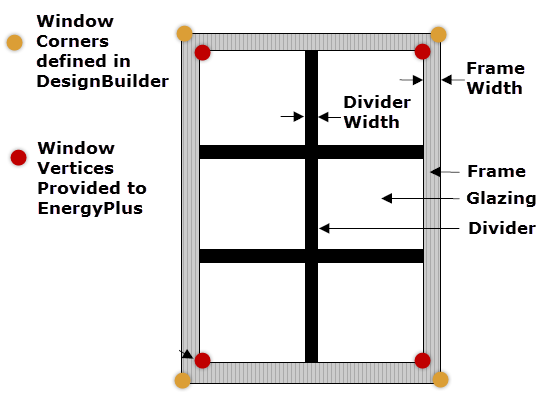
A frame surrounds the glazing in a rectangular window (schematics below). It is assumed that all frame characteristics, such as width, conductance and solar absorptance, are the same for the top, bottom and side elements of the frame. If the frame elements are not the same then you should enter area-weighted average values for the frame characteristics.
If the glazing does not have a frame or dividers or if the whole glazing assembly properties are being modelled directly using the 2-Simple glazing definition method then you should uncheck the Has frame/dividers box.
If Has frame/dividers is checked and then you can enter:
EnergyPlus window dimensions - technical information
For external windows on walls the following dimensions in the direction of the glazing normal can also be entered:
The definition of the above dimensions is shown in the diagrams.
Reveal surfaces are associated with the setback of the glazing from the outside/inside surfaces of the wall they are located in. If the depth and solar absorptance of these surfaces are specified, the program will calculate the reflection of beam solar radiation from these surfaces. The program also calculates the shadowing (onto the window) of beam and diffuse solar radiation by outside reveal surfaces.
The following fields specify the properties of the window reveal surfaces (reveals occur when the window is not in the same plane as the base surface). From this information and from the geometry of the window and the sun position, the program calculates beam solar radiation absorbed and reflected by the top, bottom, right and left sides of outside and inside window reveal surfaces. In doing this calculation, the shadowing on a reveal surface by other reveal surfaces is determined using the orientation of the reveal surfaces and the sun position.
It is assumed that:
The schematics below show how DesignBuilder reveal data is used to describe real glazing systems.
Although it is possible for inside reveal depth to be calculated from the outside reveal depth and the wall thickness, DesignBuilder allows both Inside and Outside reveal depths to be defined giving greater flexibility for situations where it is not possible to enter the wall thickness as accurately as one might like. For example the wall thickness may be entered as zero for simplified modelling. In such cases having direct control over the reveal depth data is an advantage.
The inside reveal depth is the distance (in m or ft) from the innermost surface of the window to the interior wall surface as shown in the diagram above. This setting is used for EnergyPlus simulations but not for Visualisations and Radiance which use the Outside reveal depth to define the position of the window within the wall.
Note: Inside reveal depth data is provided to EnergyPlus in the same object as the frame and divider data, so when the Has frame/dividers option is unchecked this data is not provided to EnergyPlus and the equivalent of a 0 inside reveal depth will be simulated.
See also Outside reveal depth.
The inside sill depth is the distance (in m or ft) from the innermost surface of the window to the innermost end of the sill as shown in the diagram above.
Note: Inside sill depth data is provided to EnergyPlus in the same object as the frame and divider data, so when the Has frame/dividers option is unchecked this data is not provided to EnergyPlus and the equivalent of a 0 inside sill depth will be simulated.
Select the construction used to define the thermal properties of both the frame and dividers. In particular the frame construction is used to derive these EnergyPlus frame-related fields:
Frame conductance
The effective thermal conductance of the frame (in W/m2-K or Btu/h-ft2-F) measured from inside to outside frame surface excluding surface air films and taking frame and window geometry as associated 2-D conduction effects into account. Ideally the frame conductance should be obtained from THERM or some other 2-D calculation. DesignBuilder calculates the surface to surface conductance simply based on the material layers in the Frame construction. If you need to include particular 2-D conduction effects for the frame conductance then you should adjust the thickness or material properties of the layers of the frame construction.
Note: For metal frame windows DesignBuilder will calculate a very high surface to surface U-value for the frame construction, but the value that will be provided to EnergyPlus is limited to an maximum value of 500 W/m2k. This is in line with the limits used in the LBNL WINDOW program. This will have negligible difference on simulation as the corresponding thermal resistance is effectively zero in both cases (relative to the inside and outside film resistances).
Frame solar absorptance
The solar absorptance of the frame is derived from the surface properties of the outermost material layer. The value is assumed by EnergyPlus to be the same on the inside and outside of the frame and to be independent of angle of incidence of solar radiation. If solar reflectance (or reflectivity) data is available, then absorptance is equal to 1.0 minus reflectance (for opaque materials).
Frame visible absorptance
The visible absorptance of the frame is derived from the surface properties of the outermost material layer. The value is assumed to be the same on the inside and outside of the frame and to be independent of angle of incidence of solar radiation. If visible reflectance (or reflectivity) data is available, then absorptance is equal to 1.0 minus reflectance (for opaque materials).
Frame thermal hemispherical emissivity
The thermal emissivity of the frame is derived from the surface properties of the outermost material layer and is assumed the same on the inside and outside.
The width of the frame elements when projected onto the plane of the window (in m or ft). It is assumed that the top, bottom and side elements of the frame have the same width. If not, an average frame width should be entered such that the projected frame area calculated using the average value equals the sum of the areas of the frame elements.
The amount by which the frame projects outward from the outside surface of the window glazing (in m or ft). If the outer surface of the frame is flush with the glazing then enter 0. This value is used to calculate shadowing of frame onto glass, solar absorbed by frame, IR emitted and absorbed by frame, and convection from frame.
The amount by which the frame projects inward from the inside surface of the window glazing (in m or ft). If the inner surface of the frame is flush with the glazing then enter 0. This value is used to calculate solar absorbed by frame, IR emitted and absorbed by frame, and convection from frame.
The effective thermal conductance of the frame measured from inside to outside frame surface (no air films) and taking 2-D conduction effects into account. Obtained from WINDOW or other 2-D calculation.
The glass conductance near the frame (excluding air films) divided by the glass conductance at the centre of the glazing (excluding air films). Used only for multi-pane glazing constructions. This ratio is greater than 1.0 because of thermal bridging from the glazing across the frame and across the spacer that separates the glass panes. Values can be obtained from WINDOW for the user-selected glazing construction and frame characteristics.
Dividers split the glazing up into separate lites. It is assumed that all divider elements have the same characteristics. If not, area-weighted average values should be used.
The schematic below show how DesignBuilder divider data is used to describe real glazing systems.
The type of divider can be selected from these options:
The width of the divider elements when projected onto the plane of the window (in m or ft). It is assumed that the horizontal and vertical divider elements have the same width. If not, an average divider width should be entered such that the projected divider area calculated using the average value equals the sum of the areas of the divider elements.
The number of divider elements parallel to the top and bottom of the window.
The number of divider elements parallel to the sides of the window.
The amount by which the divider projects out from the outside surface of the window glazing (in m or ft). For Divider Type = Suspended, Divider Projection = 0.0. Used to calculate shadowing of divider onto glass, solar absorbed by divider, IR emitted and absorbed by divider, and convection from divider.
The amount by which the divider projects inward from the inside surface of the window glazing (in m or ft). If the inner surface of the divider is flush with the glazing, enter 0.0. Used to calculate solar absorbed by divider, IR emitted and absorbed by divider, and convection from divider.
The glass conductance near the divider (excluding air films) divided by the glass conductance at the centre of the glazing (excluding air films). Used only for multi-pane glazing constructions. This ratio is greater than 1.0 because of thermal bridging from the glazing across the divider and across the spacer that separates the glass panes. Values can be obtained from the WINDOW program for the user-selected glazing construction and divider characteristics.
The Construction is used to define the thermal properties of both the frame and dividers. In particular the frame construction is used to derive these EnergyPlus divider-related fields:
Divider conductance
The effective thermal conductance of the divider (in W/m2-K or Btu/h-ft2-F) measured from inside to outside divider surface excluding surface air films and taking 2-D conduction effects into account. Obtained from WINDOW 6 or other 2-D calculation. DesignBuilder calculates the surface to surface conductance simply based on the material layers. If you need to include particular 2-D conduction effects for the frame/divider conductance then you should adjust the thickness or material properties of the layers of the frame construction.
Divider solar absorptance
The solar absorptance of the divider is derived from the surface properties of the outermost material layer. The value is assumed to be the same on the inside and outside of the divider and to be independent of angle of incidence of solar radiation. If solar reflectance (or reflectivity) data is available, then absorptance is equal to 1.0 minus reflectance (for opaque materials).
Divider visible absorptance
The visible absorptance of the divider is derived from the surface properties of the outermost material layer. The value is assumed to be the same on the inside and outside of the divider and to be independent of angle of incidence of solar radiation. If visible reflectance (or reflectivity) data is available, then absorptance is equal to 1.0 minus reflectance (for opaque materials).
Divider thermal hemispherical emissivity
The thermal emissivity of the divider, assumed to be the same on the inside and outside.
Note 1: If you do not wish to model the shading/reflection effect of the reveal/frame/divider then simply set the projection/depth to zero.
Note 2: In the case where a window blind is applied mid-pane, any dividers that may have been specified for the window will not be applied in the model. EnergyPlus will generate a warning to this effect.