There are two general approaches to natural ventilation and infiltration modelling in DesignBuilder depending on the setting of the Natural ventilation model option:
You can choose Scheduled natural ventilation if you are able to make a reasonable estimate of the natural ventilation rates and infiltration rates in the building. Other airflow scenarios are more difficult to estimate and in this case it may be necessary to calculate airflows.
Scheduled Natural Ventilation flow rate and schedule data is accessed on the HVAC tab. The flow is switched off if the zone air temperature falls below the Ventilation setpoint temperature set under Environmental Control on the Activity tab.
Infiltration is defined by a constant ACH value under Airtightness on the Construction tab.
Airflow through Exterior Windows, Vents and Doors is considered to be included in the Natural ventilation outside air ac/h value set on the HVAC tab.
Airflows between zones can be defined using the Interzone Airflow dialog.
Also, airflow through Interior Windows, Vents and Doors can be modelled using the concept of mixing where equal amounts of air are transferred from one zone to another and vice-versa. The flow rate is directly proportional to the opening area using Airflow rate per opening area data accessed from the Model options dialog.
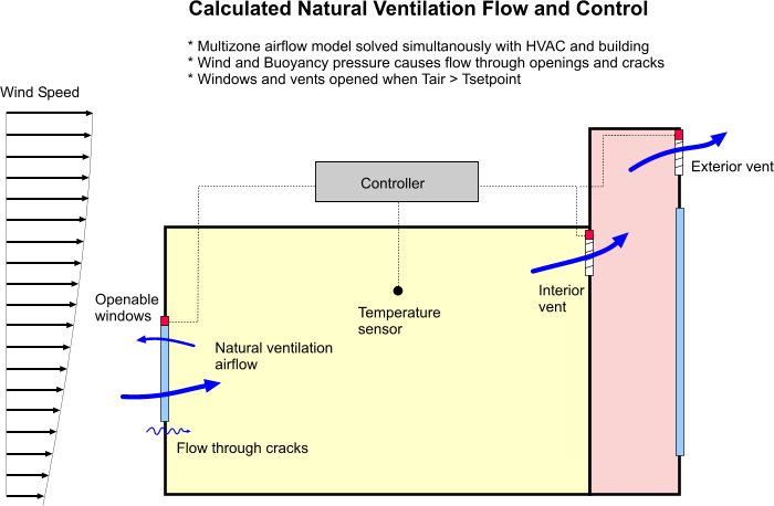
By default Calculated natural ventilation is controlled by timer (window and vent data on the Operation header on the Openings tab) and by Ventilation setpoint temperature on the Activity tab.
The Crack data under Airtightness on the Constructions tab is used in the EnergyPlus Airflow Network to calculate infiltration.
Note 1: Using the Calculated option increases the complexity of the model and slows simulations down. You should aim to simplify the model as appropriate to the requirements of the calculations. For example if you are carrying out a summertime simulation of a naturally ventilated building you could consider switching off infiltration modelling if infiltration heat flow is only a very small part of summertime heat balance.
Note 2: In Version 1 the calculated airflows through external windows, vents, doors, holes and cracks are all lumped into 'External air' data on the Simulation results screen.
The ventilation rate (q) through each opening and crack in the model is calculated based on the pressure difference using wind and stack pressure effects:
q = C.(DP) n
Where:
q is the volumetric flow through the opening.
DP is the pressure difference across the opening/crack.
n is the flow exponent varying between 0.5 for fully turbulent flow and 1.0 for fully laminar flow.
C is the flow coefficient, related to the size of the opening/crack.
When wind impinges on the surface of a rectangular building, a positive pressure is induced on the upwind face. The flow separates at the corners resulting in negative pressure regions on the side of the building and a negative pressure distribution on the leeward facade. The pressure distribution on the roof varies according to pitch - the pressure on the upwind face being negative for roof pitches of 30° and positive for steeper pitches.
The pressure on any point on the surface of a building facade can be represented by:
Pw = 0.5 .rho. Cp . vz2
Where:
Pw is the surface pressure due to wind,
rho is the density of air,
Cp is the wind pressure coefficient at a given position on the surface and
vz is the mean wind velocity at height z.
The wind pressure coefficient, Cp, is a function of wind direction, position on the building surface and side exposure. Some typical approximate values for buildings subjected to varying degrees of shelter and wind directions is given in an AIVC publication A guide to energy-efficient ventilation. This data is also quoted in the CIBSE A Guide. DesignBuilder uses this data to populate the Pressure Coefficients templates and provide default pressure coefficients suitable for use in basic design calculations for buildings having no more than three stories.
For more detailed analysis, or for buildings having 4 or more stories you should obtain specific pressure coefficient data from CFD analysis of from wind tunnel measurements and enter it for each surface under the Pressure Coefficients header on the Openings tab.
When carrying out conservative design calculations you may prefer to exclude (or reduce) the effects of wind from Calculated natural ventilation. To exclude wind-driven airflow from the analysis altogether set the Wind factor to 0. For full treatment of wind effects set it to 1 and for intermediate treatment of wind set to a number between 0 and 1.
DesignBuilder uses the EnergyPlus Airflow Network method to calculate air flow rates. You should be aware
Airflow Network simulations can take considerably longer than the equivalent simulations with Scheduled natural ventilation.
You can modulate the opening sizes to reduce the large temperature swings that can occur if the windows/doors are too far open when they are venting, especially when there is a large inside-outside temperature difference. Use the Modulation settings on the Advanced tab of the Model Options dialog to control this. By default modulation is on and opening sizes are reduced to 5% of full values when the outside is 15°C or more colder than inside. This models the fact that occupants are unlikely to throw the windows wide open when it is very cold outside (for manual control systems).
Normally when Calculated natural ventilation is set DesignBuilder includes a single crack in each surface in the simulation to account for infiltration. The size and properties of this crack depend on the setting of the Airtightness slider.
Tip: The effects of infiltration in some areas of the building and in some calculation types can be minor and so in order to reduce simulation time for calculated natural ventilation models infiltration can be switched off. This can be done by unchecking the Model infiltration checkbox for the areas of the building where infiltration in not to be modelled. For example you may wish to switch off infiltration in roof blocks (and include the roofspace ventilation using a smaller number of vents or holes instead) or you could switch it off in the whole building for Summertime simulations where the effects of infiltration would be minimal relative to the much larger flow rates due to open windows, vents, holes and doors.
The setting of the Airtightness slider indicates the Crack template applied when setting crack properties:
See also Mixed mode.
You can find more technical details of the Airflow network used in EnergyPlus including background, algorithms, limitations and validation results in a paper by Lixing Gu at: