![]() Chiller:Electric:EIR
Chiller:Electric:EIR
Used in:
- Chilled water loop, supply side
|
|
|
Used in:
|
This chiller model is the empirical model used in the DOE-2.1 building energy simulation program. It uses performance information at reference conditions along with three curve fits for cooling capacity and efficiency to determine chiller operation at off-reference conditions. Chiller performance curves can be generated by fitting manufacturer’s catalog data or measured data. Performance curves for more than 300 chillers, including the default DOE-2.1E reciprocating and centrifugal chillers, are provided as templates for selection within the chiller dialog. This data comes from in the EnergyPlus Reference DataSets (Chillers.idf).
 See the Chilled Water Loop and FCU Tutorial
Note: Chiller:Electric:EIR objects and their associated performance curve objects are developed using performance information for a specific chiller and should normally be used together for an EnergyPlus simulation. Changing the object input values, or swapping performance curves between chillers, should be done with caution.
The auto-generated name of the chiller can be edited.
Use this browse option to select a chiller from the EnergyPlus chiller database whose performance data you wish to copy to your chiller.
The type of chiller can be one of these options:
The Chiller type cannot be edited directly. To use a different type you must add a new chiller, selecting the appropriate type from the drop list.
This numeric field contains the reference cooling capacity of the chiller (in W or Btu/h). This should be the capacity of the chiller at the reference temperatures and water flow rates defined below. Alternatively, this field can be autosized.
This numeric field contains the chiller’s coefficient of performance which is multiplied by the output of the chiller performance curves described below. This value should not include energy use due to pumps, evap-cooled or air-cooled condenser fans, or cooling tower fans. This COP should be at the reference temperatures and water flow rates defined below.
This numeric input represents the fraction of compressor electrical energy consumption that must be rejected by the condenser. Enter a value of 1.0 when modelling hermetic chillers. This value must be between 0.0 and 1.0, with a default value of 1.0.
This choice field determines how the chiller operates with respect to the intended fluid flow through the device’s evaporator. There are three choices for specifying operating modes for the intended flow behaviour:
In all cases the operation of the external plant system can also impact the flow through the chiller - for example if the relative sizes and operation are such that flow is restricted and the requests cannot be met.
For variable flow chilled water loops these options are available: 2-Leaving setpoint modulated and 3-Not modulated.
For constant flow chilled water loops these options are available: 1-Constant flow and 3-Not modulated.
The type of loop (variable/constant flow) can be changed by modifying the Plant loop flow type on the Chilled water plant loop dialog.
Note: When the 2-Leaving setpoint modulated option is selected then you must add an extra Setpoint manager immediately downstream of the chiller chilled water outlet to define the temperature of the water supplied.
The sizing factor is used when the chiller design inputs are autosized. In this case the autosizing results are multiplied by this additional sizing factor. The usual value to enter is 1.0.
The inputs that would be altered by the sizing factor are: Reference capacity, Reference chilled water flow rate and Reference condenser water flow rate.
The most common use of the sizing factor is for sizing chillers to meet only part of the design load while continuing to use the autosizing feature. For example when a set of chillers is chained together to supply chilled water to a plant loop, this sizing factor can be used to indicate the proportion of the load to be met by each chiller.
See also the section on Autosizing HVAC Components
The condenser type determines what type of condenser will be included with this chiller. Valid condenser types are:
The default is 2-Water cooled which requires the full specification of the Condenser loop and its associated equipment. 1-Air cooled and 3-Evaporatively cooled do not require a Condenser loop to be specified.
Note: Condenser type cannot be edited directly. To help you to ensure that appropriate performance curves are used, load a chiller of the correct type from the Chiller template.
This data is used to model condenser fan power associated with air-cooled or evaporatively cooled condensers. Enter the ratio of the condenser fan power to the reference chiller cooling capacity in W/W.
During the simulation the condenser fan power for air-cooled or evaporatively cooled chillers is calculated as total chiller power consumption multiplied by this ratio.
This numeric field contains the chiller’s reference leaving chilled water temperature (in °C or °F). The default value is 6.67°C.
This numeric field contains the chiller’s reference entering condenser fluid temperature (in °C or °F). The default value is 29.4°C. For water-cooled chillers this is the water temperature entering the condenser (e.g., leaving the cooling tower). For air- or evap-cooled condensers this is the entering outdoor air dry-bulb or wet-bulb temperature, respectively.
This numeric field contains the lower limit for the leaving chilled water temperature (in °C or °F). This temperature acts as a cut off for heat transfer in the evaporator, so that the fluid doesn’t get too cold. The default value is 2˚C.
Note: This input field is currently unused.
For a variable flow chiller this is the maximum water flow rate and for a constant flow chiller this is the operating water flow rate through the chiller’s evaporator. The units are (in m3/s or gal/min). This numeric input field must be greater than zero, or it can be autosized.
This numeric field contains the chiller’s operating condenser water flow rate (in m3/s or gal/min). This field can be autosized.
The name of a Bi-quadratic performance curve that parameterizes the variation of the cooling capacity as a function of the leaving chilled water temperature and the entering condenser fluid temperature. The output of this curve is multiplied by the reference capacity to give the cooling capacity at specific temperature operating conditions (i.e., at temperatures different from the reference temperatures). The curve should have a value of 1.0 at the reference temperatures and flow rates specified above. The bi-quadratic curve should be valid for the range of water temperatures anticipated for the simulation.
The name of a Bi-quadratic performance curve that parameterizes the variation of the energy input to cooling output ratio (EIR) as a function of the leaving chilled water temperature and the entering condenser fluid temperature. The EIR is the inverse of the COP. The output of this curve is multiplied by the reference EIR (inverse of the reference COP) to give the EIR at specific temperature operating conditions (i.e., at temperatures different from the reference temperatures). The curve should have a value of 1.0 at the reference temperatures and flow rates specified above. The bi-quadratic curve should be valid for the range of water temperatures anticipated for the simulation.
The name of a Quadratic performance curve that parameterizes the variation of the energy input ratio (EIR) as a function of the part-load ratio. The EIR is the inverse of the COP, and the part-load ratio is the actual cooling load divided by the chiller’s available cooling capacity. The output of this curve is multiplied by the reference EIR (inverse of the reference COP) and the Energy input to cooling output ratio function of temperature curve to give the EIR at the specific temperatures and part-load ratio at which the chiller is operating. This curve should have a value of 1.0 when the part-load ratio equals 1.0. The quadratic curve should be valid for the range of part-load ratios anticipated for the simulation.
During the simulation the electric power consumption of the compressor is calculated using:
Qcompressor = (Qref / CoPref) * CAPFT * EIRFT * EIRPLR
Where CAPFT, EIRFT and EIRPLR are the outputs from the 3 curves above.
If you have manufacturers data you can generate the inputs for these 3 curves using the spreadsheet provided free by EnergyPlus called Chiller_PerformanceCurve_Coefficients.xls. When using this spreadsheet to generate inputs for EIRPLR note that the coefficients are read from the spreadsheet into the DesignBuilder Quadratic Curve dialog as follows:
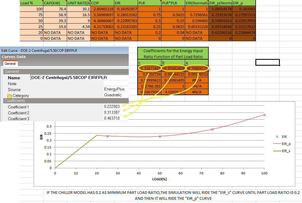
Of course the performance and capacity of a chiller depends on various factors, the most important of these being part load and temperature chilled water and the Chiller EIR provides an accurate representation taking these factors into account. However in some cases you may only have summary manufacturers data. For example you may only have information on the variation of CoP with part load ratio. In this case you can define the EIRPLR curve in the usual way using your summary manufacturer’s data and use constant values for the CAPFT and EIRFT curves which both generate a constant value of 1.0. Because CAPFT and EIRFT are both Bi-quadratic curves you cannot use a constant Linear curve here so you must choose inputs to a special simple Bi-quadratic curve that generates an output of 1 regardless of inputs. To achieve this simply create and select a new Bi-quadratic curve with Coefficient 1 = 1 and all other coefficients = 0 for CAPFT and EIRFT.
This numeric field contains the chiller’s minimum part-load ratio. The expected range is between 0 and 1. Below this part-load ratio, the compressor cycles on and off to meet the cooling load. The Minimum part load ratio must be less than or equal to the Maximum part load ratio. The default value is 0.1.
Note: Setting the Minimum part load ratio to zero for air cooled chillers, will cause the condenser fan to run constantly even at zero load which is likely to lead to high chiller fan consumption. This happens because the condenser fan cannot cycle off even at zero chiller load.
This numeric field contains the chiller’s maximum part-load ratio. This value may exceed 1, but the normal range is between 0 and 1.0. The Maximum part load ratio must be greater than or equal to the Minimum part load ratio. The default value is 1.0.
This numeric field contains the chiller’s optimum part-load ratio. This is the part-load ratio at which the chiller performs at its maximum COP. The optimum part-load ratio must be greater than or equal to the Minimum part load ratio, and less than or equal to the Maximum part load ratio. The default value is 1.0.
This numeric field contains the chiller’s minimum unloading ratio. The expected range is between 0 and 1. The minimum unloading ratio is where the chiller capacity can no longer be reduced by unloading and must be false loaded to meet smaller cooling loads. A typical false loading strategy is hot-gas bypass. The minimum unloading ratio must be greater than or equal to the Minimum part load ratio, and less than or equal to the Maximum part load ratio. The default value is 0.2.
Different chiller types (reciprocating, centrifugal etc) have very different operating characteristics. The point at which they switch off at low load (cycle on and off to meet small loads) will vary between about 0.25 for older reciprocating chillers and 0.1 for modern centrifugal chillers which have much better part-load performance. Sometimes a manufacturer or installer may need to introduce a mechanism to stop the chiller cycling on and off too frequently (frequent cycling causes excessive wear and reduces the equipment life). To stop this happening some of the hot gas from the compressor outlet can be re-injected back into the return side of the compressor so that the compressor inlet senses a higher return gas temperature and is ‘fooled’ into thinking that there is a higher cooling load on the system than there actually is (this basically mimics a higher evaporator leaving temperature) so it needs to work a little harder to meet the load and the load is therefore maintained above the point at which the compressor would normally switch off. This strategy is called false-loading and it is clear that bypassing hot gas from the discharge to the suction side of the compressor results in higher energy consumption so is generally not considered to be an acceptable control strategy and actually contravenes some energy codes (e.g. Part L2 in UK). This strategy is sometimes used to overcome poor design and control problems.
You can avoid false loading in your model by setting the Minimum unloading ratio equal to the Minimum part load ratio, so when the chiller reaches its minimum part-load ratio it just switches off and false-loading cannot occur.
Many output variable names are common across all chiller types. These generic chiller output names all begin with the word "Chiller". Certain chiller types have additional output variables which are specific to that type of chiller. Specific chiller output names begin with the chiller type, for example, "Gas Absorption Chiller Heating Energy [J]." Chiller energy use is added to the appropriate plant-level meters as a cooling end-use.
HVAC,Average,Chiller Electric Power [W]
HVAC,Sum,Chiller Electric Consumption [J]
Zone,Meter,Electricity:Plant [J]
Zone,Meter,Cooling:Electricity [J]
HVAC,Average,Chiller Evap Heat Trans Rate [W]
HVAC,Sum,Chiller Evap Heat Trans [J]
Zone,Meter,EnergyTransfer:Plant [J]
Zone,Meter,Chillers:EnergyTransfer [J]
HVAC,Average,Chiller Evap Water Inlet Temp [C]
HVAC,Average,Chiller Evap Water Outlet Temp [C]
HVAC,Average,Chiller Evap Water Mass Flow Rate [kg/s]
HVAC,Average,Chiller Cond Heat Trans Rate [W]
HVAC,Sum,Chiller Cond Heat Trans [J]
Zone,Meter,HeatRejection:EnergyTransfer [J]
HVAC,Average,Chiller COP [W/W]
The following output is applicable only for air-cooled or evap-cooled chillers:
HVAC,Average,Chiller Cond Air Inlet Temp [C]
The following outputs are applicable only for evap-cooled chillers:
HVAC,Average,Chiller Basin Heater Electric Power [W]
HVAC,Average,Chiller Basin Heater Electric Consumption [J]
The following three outputs are only available for water-cooled chillers:
HVAC,Average,Chiller Cond Water Inlet Temp [C]
HVAC,Average,Chiller Cond Water Outlet Temp [C]
HVAC,Average,Chiller Cond Water Mass Flow Rate [kg/s]
HVAC,Average,Chiller Shaft Power [W]
These outputs are the electric power input to the chiller. In the case of steam or fuel-powered chillers, this repesents the internal chiller pumps and other electric power consumption. Consumption is metered on Cooling:Electricity, Electricity:Plant, and Electricity:Facility.
These outputs are the evaporator heat transfer which is the cooling delivered by the chiller. Chiller Evap Heat Trans is metered on Chillers:EnergyTransfer, EnergyTransfer:Plant, and EnergyTransfer:Facility.
These outputs are the evaporator (chilled water) inlet and outlet temperatures and flow rate.
This output is the coefficient of performance for the chiller during cooling operation. It is calculated as the evaporator heat transfer rate (Chiller Evap Heat Trans Rate) divided by the “fuel” consumption rate by the chiller. For the constant COP and electric chillers, the “fuel” is electricity so the divisor is Chiller Electric Power [W]. For the absorption chiller, the “fuel” is steam so the divisor is Steam Consumption Rate [W].
For the engine driven chiller and combustion turbine chiller, the output variable is renamed as Chiller Fuel COP to clarify that the primary energy input to the chiller is a gaseous or liquid fuel (natural gas, diesel, gasoline, etc.). The divisor is the appropriate fuel consumption rate (Chiller [fuel type] Consumption Rate).
For the direct fired absorption chiller, this variable is renamed as Direct Fired Absorption Chiller Cooling Fuel COP and the divisor is Direct Fired Absorption Chiller Cooling Gas Consumption Rate.
Note that this variable is reported as zero when the chiller is not operating. When reported for frequencies longer than "detailed" (such as timestep, hourly, daily, monthly or environment), this output will only be meaningful when the chiller is operating for the entire reporting period. To determine an average COP for a longer time period, compute the COP based on total evaporator heat transfer divided by total electric or fuel input over the desired period.
This output is the operating part-load ratio of the indirect absorption chiller. This output may fall below the minimum part-load ratio specified in the input. For this case, the Chiller Cycling Fraction is used to further define the performance of the indirect absorption chiller.
This output is the fraction of the timestep the indirect absorption chiller operates. When the chiller operates above the minimum part-load ratio, a chiller cycling fraction of 1 is reported. When the chiller operates below the minimum part-load ratio, the chiller cycling fraction reports the fraction of the timestep the indirect absorption chiller operates.
These outputs are the condenser heat transfer which is the heat rejected from the chiller to either a condenser water loop or through an air-cooled condenser. Chiller Cond Heat Trans is metered on HeatRejection:EnergyTransfer, EnergyTransfer:Plant, and EnergyTransfer:Facility.
This output is the condenser (heat rejection) inlet temperature for air-cooled or evap-cooled chillers. For an air-cooled chiller, this output would be the dry-bulb temperature of the air entering the condenser coil. For an evap-cooled chiller, this output would be the wet-bulb temperature of the air entering the evaporatively-cooled condenser coil.
These outputs are the electric power input to the chiller’s basin heater (for evaporativelycooled condenser type). Consumption is metered on Chillers:Electricity, Electricity:Plant, and Electricity:Facility
These outputs are the condenser (heat rejection) inlet and outlet temperatures and flow rate for water-cooled chillers.
For engine-driven and turbine-driven chillers, these outputs are the shaft power produced by the prime mover and transferred to the chiller compressor.
For chillers with heat recovery, such as engine-driven chillers, these outputs are the components of recoverable energy available. For a given chiller type, one or more of the following components may be applicable: Lube (engine lubricant), Jacket (engine coolant), Exhaust (engine exhaust), and Total. Chiller Lube Heat Recovery, Chiller Jacket Heat Recovery, and Chiller Exhaust Heat Recovery are metered on HeatRecovery:EnergyTransfer, EnergyTransfer:Plant, and EnergyTransfer:Facility.
This is the exhaust temperature leaving an engine chiller.
These outputs are the heat recovery inlet and outlet temperatures and flow rate for chillers with heat recovery such as engine-driven and gas turbine chillers.
These outputs are the steam or fuel input for steam or fuel-fired chillers. Valid fuel types depend on the type of chiller. <FuelType> may be one of: Gas (natural gas), Steam, Propane, Diesel, Gasoline, FuelOil#1, and FuelOil#2. Consumption is metered on Cooling:<FuelType>, <FuelType>:Plant, and <FuelType>:Facility.
These reports are available only for Electric EIR Chillers.
These outputs are for the electric power consumption of the chiller condenser fan and are applicable to air- or evaporatively-cooled chillers. This output is also added to a report meter with Resource Type = Electricity, End Use Key = Chillers, Group Key = Plant (Ref. Report Meter).
This is the output of the curve object Cooling Capacity Function of Temperature Curve.
This is the output of the curve object Electric Input to Cooling Output Ratio Function of Temperature Curve.
This is the output of the curve object Electric Input to Cooling Output Ratio Function of Part Load Curve.
This output is the ratio of the evaporator heat transfer rate plus the false load heat transfer rate (if applicable) to the available chiller capacity. This value is used to determine ChillerEIRFPLR.
The cycling ratio is the amount of time the chiller operates during each simulation timestep. If the chiller part-load ratio falls below the minimum part-load ratio, the chiller cycles on and off to meet the cooling load.
These outputs are the heat transfer rate and total heat transfer due to false loading of the chiller. When the chiller part-load ratio is below the minimum unloading ratio, the chiller false loads (e.g. hot-gas bypass) to further reduce capacity. The false load heat transfer report variable is not metered.