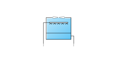
Cooling towers are the main active component within condenser loops. The cooling tower is modelled as a counter-flow heat exchanger with a single-speed fan (induced draft configuration) based on Merkel’s theory. The user must define tower performance via one of two methods: design heat transfer coefficient-area product (UA) and design water flow rate, or nominal tower capacity at a specific rating point. Regardless of which method is chosen, the design airflow rate and corresponding fan power must be specified. The model will also account for tower performance in the “free convection” regime, when the tower fan is off but the water pump remains on and heat transfer still occurs (albeit at a low level). If the user wants the model to account for “free convection”, they must specify the corresponding airflow rate and heat transfer coefficient-area product (UA), or the nominal tower capacity during this mode of operation.
 The Condenser Loop Tutorial includes a useful description of cooling tower operating principles and the Cooling tower dialog
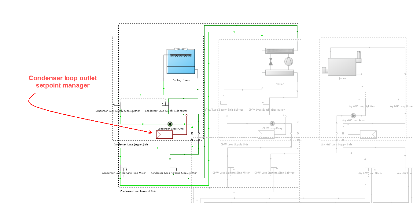
The cooling tower seeks to maintain the temperature of the water exiting the cooling tower at (or below) a set point. The set point schedule value is defined by the condenser loop outlet setpoint manager:
The model first checks to determine the impact of “free convection”, if specified by the user, on the tower exiting water temperature. If the exiting water temperature based on “free convection” is at or below the set point, then the tower fan is not turned on. If the exiting water temperature based on “free convection” is below the set point, the tower will operate in Fluid bypass mode whereby a portion of the water goes through the tower media and gets cooled while the remaining water flow gets bypassed, two water flows then mix together trying to meet the water setpoint temperature. If the exiting water temperature remains above the set point after “free convection” is modelled, then the tower fan is turned on to reduce the exiting water temperature to the set point. If the capacity control is 1-Fan cycling, the model assumes that part-load operation is represented by a simple linear interpolation between two steady-state regimes (i.e. the tower fan is on for the entire simulation time-step and the tower fan is off for the entire simulation time-step). Cyclic losses are not taken into account. If the capacity control is 2-Fluid bypass, the model determines the fraction of water flow to be bypassed while the remaining water goes through the tower cooling media and gets cooled, then the two water flows mix to meet the setpoint temperature. In this case, the fan runs at full speed for the entire time-step.
Cooling towers here are “wet” and consume water through evaporation, drift, and blow-down. The model can be used to predict water consumed by the towers.
For the operation of multi-cell towers, the first step is to determine the number of cells to operate based on the cell control method, between the minimum number of cells subject to the maximum water flow rate fraction per cell and maximum number of cells subject to the minimum water flow rate fraction per cell. If the calculated cells do not meet the loads, additional cells will be operating to help meet the loads. Inside each cell, the existing capacity controls still apply.
For multi-cell towers, the following inputs are assumed to be for the entire tower including all cells:
To edit the data associated with a cooling tower, you first need to select the component by moving the mouse cursor over it and then clicking the mouse button to select it. You can then access the edit dialog by right-clicking the mouse and selecting the Edit selected component option or alternatively, select the Edit selected component tool from the toolbar.
The schematic diagrams below (reproduced with permission from CIBSE) illustrate the various types of Direct & Indirect Heat Rejection used in cooling towers. The condenser process takes the fluid from saturated vapour (point 5) to saturated liquid (point 6) on the graph below.
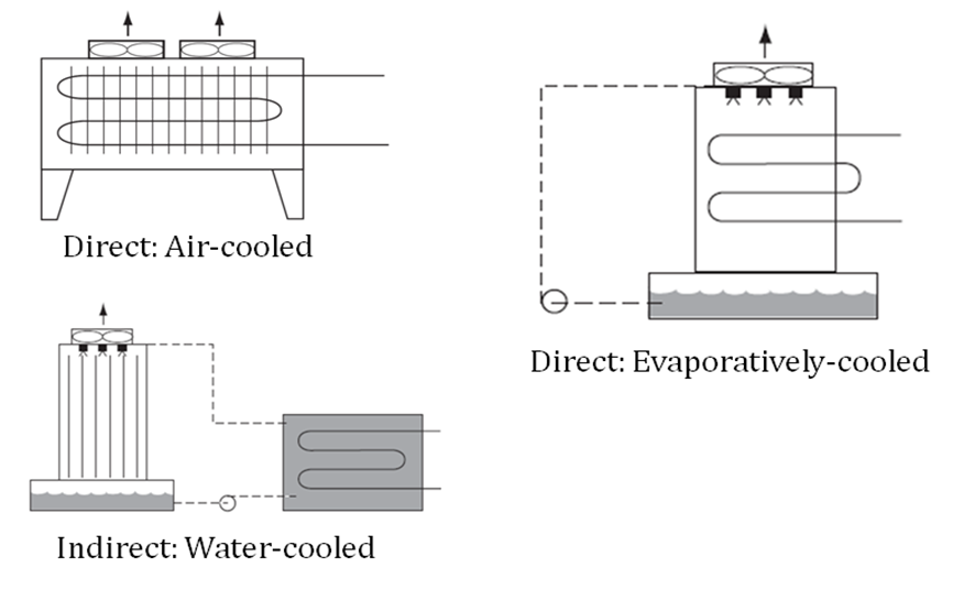
Direct & Indirect Heat Rejection (CIBSE Guide B Table 4.10)
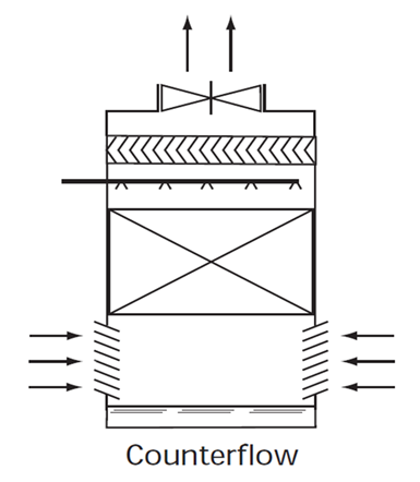
Induced Draft Cooling Tower (CIBSE Guide B Table 4.22)
This is the name that you assign to the cooling tower which should be unique. If the supplied name is not unique, the software will automatically append a backslash and integer to ensure that there are no duplicate names.
This numeric field contains the design air flow rate induced by the tower fan (in m3/s or ft3/min). A value of greater than zero must be defined regardless of the tower performance input method. Alternately, this field can be autosized. If autosized, the design air flow rate is calculated as follows:

In which a fan pressure rise of 190 Pa and total fan efficiency of 0.5 are assumed.
This is the fan power (W) at the design air flow rate specified under Design air flow rate. A value of greater than zero must be specified regardless of the tower performance input method, or alternatively, this field can be autosized. If autosized, the fan power is calculated as follows:
If Performance input method is specified as 1-Nominal capacity, then the fan power is obtained from:

If Performance input method is specified as 2-UA and Design water flow rate, then the fan power is obtained from:

This is the air flow rate (in m3/s or ft3/min) when the tower is in the “free convection” regime (water flow exists but tower fan is turned off). This value must be less than the value specified for the field Design air flow rate. This setting may be autosized, in which case it is set to 10% of the Design air flow rate. If the you do not wish to model “free convection” and are using the Performance input method 2-UA and Design water flow rate option, then this setting should be set to 0.0. If you specify the UA at free convection air flow rate or Free convection capacity as a value greater than zero, then the free convection air flow rate must be specified greater than 0.0.
This field is used to choose which method is used to model the amount of water evaporated by the cooling tower. There are two options:
The default is 1-Saturated exit. The user-defined loss factor is entered under Evaporation loss factor, below. By assuming that the air leaving the tower is saturated, the evaporation can be directly calculated using moist air engineering calculations with data available within the cooling tower model (and does not require additional user input).
This field is used to specify the rate of water evaporated from the cooling tower and lost to the outside air (in %/K or %/F). This field is only available if the Evaporation loss mode (above) is set to 2-Loss factor. The evaporation loss is then calculated as a fraction of the circulating condenser water flow and varies with the temperature change in the condenser water. The evaporation rate will equal this value times each degree Kelvin of temperature drop in the condenser water. Typical values are from 0.15 to 0.27 (%/K). The default is 0.2.
This field is used to specify the rate of water lost to the exiting air as entrained droplets (%). The drift loss is a percent of the condenser water flow. Typical values for towers with efficient drift eliminators are between 0.002 and 0.2% of the condenser water flow rate. The default value is 0.008%.
This setting allows the user to specify a sizing factor for this component. The sizing factor is used when the component design inputs are auto-sized. In this case the auto-sizing calculations are performed as usual and the results are multiplied by the sizing factor. Sizing factor allows the user to size a component to meet part of the design load while continuing to use the auto-sizing feature. For this component the inputs that would be altered by the sizing factor are:
See also the section on Autosizing HVAC Components
This setting allows the method by which the user will specify tower performance to be selected. There are two options:
This is the design water flow rate through the tower (in m3/s or gal/min). This value is the flow rate of the condenser loop water being cooled by the tower (not the flow rate of water being sprayed on the outside of the heat exchange coil). If the Performance input method is specified as 2-UA and design water flow rate, then a water flow rate greater than zero must be defined or the item can be auto-sized. If auto-sized, the design water flow rate is derived from the design load to be rejected by the condenser loop and the design loop temperature difference. If Performance input method is specified as 1-Nominal capacity, then the model automatically assumes a water flow rate of 5.382E-8 m3/s per W of tower capacity.
This is the heat transfer coefficient-area product (UA) (in W/K or Btu/h-F) corresponding to the design air and water flow rates specified above. If the Performance Input Method is specified as 2-UA and design water flow rate, then a UA value greater than zero but less than or equal to 300,000 W/K must be defined, or the setting can be autosized. If autosized, the design tower UA value is derived from the design load to be rejected by the condenser loop and the design loop delta T, assuming a tower water inlet temperature of 35°C and tower inlet air at 35°C dry-bulb/25.6°C wet-bulb.
This is the heat transfer coefficient-area product (W/K or Btu/h-F) when the tower is in the “free convection” regime (water flow exists but tower fan is turned off). This value must be less than the value specified for the field U-Factor Times Area Value at Design Air Flow Rate. This field may be autosized, in which case it is set to 10% of the UA at design air flow rate. If you do not wish to model “free convection” and are using the Performance input method 2-UA and design water flow rate, then this setting should be set to 0.0. If Performance input method is specified as 1-Nominal capacity, then EnergyPlus automatically calculates the tower UA based on the tower capacity specified under the setting Free convection capacity.
This is the “nominal” heat rejection capacity of the cooling tower (in W or Btu/h), with entering water at 35°C (95°F), leaving water at 29.4°C (85°F), entering air at 25.6°C (78°F) wet-bulb and 35°C (95°F) dry-bulb temperatures. The design water flow rate is assumed to be 5.382E-8 m3/s per watt of nominal capacity (3 gpm/ton). 125% of this nominal tower capacity gives the actual tower heat rejection at these operating conditions (based on historical assumption that the tower must dissipate 0.25W of compressor heat for every watt of heat removed by the evaporator).
This is the “nominal” heat rejection capacity of the cooling tower (in W or Btu/h) when the tower is in the “free convection” regime (water flow exists but tower fan is turned off), with entering water at 35°C (95°F), leaving water at 29.4°C (85°F), entering air at 25.6°C (78°F) wet-bulb and 35°C (95°F) dry-bulb temperatures. The design water flow rate is assumed to be 5.382E-8 m3/s per watt of nominal tower capacity (input field above). 125% of this free convection tower capacity gives the actual tower heat rejection at these operating conditions (based on historical assumption that the tower must dissipate 0.25W of compressor heat for every watt of heat removed by the evaporator). The value specified under this setting must be less than the value specified for the field Nominal capacity. If you do not wish to model “free convection”, then this field should be set to 0.0. If you specify a value greater than zero, then the Air flow rate in free convection regime setting must contain a value greater than zero.
This is the capacity of the tower’s electric basin heater (in W/K or Btu/h-F). This field is used in conjunction with the Basin Heater Setpoint Temperature. The basin heater electric power is equal to this setting multiplied by the difference between the basin heater set point temperature and the outdoor dry-bulb temperature. The basin heater only operates when the tower fan is off and water is not flowing through the tower, regardless of the basin heater schedule described below. The basin heater capacity must be greater than or equal to zero, with a default value of zero if this field is left blank.
This is the set point temperature (˚C or ˚F) for the tower’s electric basin heater. The basin heater is active when the outdoor air dry-bulb temperature falls below this setpoint temperature, as long as the tower fan is off and water is not flowing through the tower. This set point temperature must be greater than or equal to 2˚C, and the default value is 2˚C if this field is left blank.
This is the basin heater operating schedule. The basin heater operating schedule is assumed to be an on/off schedule and the heater is available to operate any time the schedule value is greater than 0. The basin heater operates when scheduled on and the outdoor air dry-bulb temperature is below the Basin Heater Setpoint Temperature. Regardless of this schedule, the basin heater may only operate when the cooling tower fan is off and water is not flowing through the tower.
This setting specifies which method is used to determine blow-down rates. There are two options:
The choice will determine which of the two models below is used. The default is 1‑Concentration ratio.
This is used to dynamically adjust the rate of blow-down in the cooling tower as a function of the rate of evaporation. Blow-down is water intentionally drained from the tower in order to offset the build up of solids in the water that would otherwise occur because of evaporation. The value entered here is dimensionless. It can be characterized as the ratio of solids in the blow-down water to solids in the make-up water. Typical values for tower operation are 3 to 5. The default value is 3.
This is the schedule used to define the amount of water (in m3/s only) flushed from the basin on a periodic basis to purge the tower of mineral scale build-up and other contaminants. This schedule is only used if the Blow-down Calculation Mode is set to 2‑Scheduled rate. The amount of water used due to blow-down depends on the makeup water quality and is specific to each geographical location. Typical values range from 0.0002 to 0.0013 m3/s (17.3 to 112.3 m3/day). This water usage is in addition to the amount of water lost to the atmosphere due to evaporation and/or drift. Since blow-down occurs when the basin water contaminant concentration is high, blow-down only occurs when the cooling tower is active and water is flowing through the tower (regardless of the water usage defined by this schedule).
This is the cooling capacity control for the cooling tower. Two choices are available:
During part-load conditions, there are two ways to maintain the exiting water temperature at the setpoint: either cycling the tower fan, or bypassing a portion of the tower water with a three-way valve. For 2‑Fluid bypass, the tower fan still runs at full speed for the entire time-step, but only a portion of the water flow goes through the cooling tower media to get cooled while the remaining portion of the water flow gets bypassed, consequently, two water flows then mix at the common water sump to meet the setpoint temperature.
This setting is used to enable a multi-cell tower to be defined.
This is the number of cells in the multi-cell cooling tower.
This specifies the method used to control the number of cells used to meet the load, the two choices are:
This is the allowable smallest fraction of the design water flow rate. Flows less than this value will commonly result in fluid distribution problems; the pressure at each nozzle will be too weak for the fluid to be sprayed out in the correct pattern, not all the fill would be wet. If this field is left blank, the default value is 0.33.
This numeric field specifies the allowable largest fraction of the design water flow rate. If this field is left blank, the default value is 2.5.