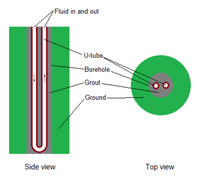
Vertical ground heat exchangers typically use boreholes containing U-tubes as shown in the figure below.
The EnergyPlus Ground Heat Exchanger (GHE) is a condenser component serving the condenser supply side alongside cooling towers and other condensing components.
The heat exchanger response is defined by a G-function. This is a non-dimensional function that is used to calculate the response to square heat pulses of different duration. (This function is not the same as ‘G-factors’ referred to in the ASHRAE Applications Handbook).
This continuous function is specified by a series of data pairs (LNTTSi, GFNCi) where:
The G-function is different for each borehole field configuration (i.e. a 4x4 field has a different response than a 80x80 field) and the borehole thermal resistance. It is also dependant on the ratio of borehole spacing to depth. G-function values, for accurate simulation, have to be calculated for each specific heat exchanger design. This can be done using some commercial ground loop heat exchanger design tool and the like. A reference data set, containing examples input data for 1x2, 4x4 and 8x8 configurations and for both standard and thermally enhanced grout, have also been provided. These data are provided as examples
only.
Further details on the implementation of this model can be found in:
Murugappan, A. Implementing Ground Source Heat Pump and Ground Loop Heat Exchanger Models in the EnergyPlus Simulation Environment. M.S. Thesis, Oklahoma State University, December 2002.
This alpha field contains the identifying name for the ground heat exchanger.
You can use this control to load data to the dialog from a pre-defined Ground heat exchanger template as a starting point for your particular component.
Note: After loading a Ground heat exchanger template it is important to make sure to update the Design and Maximum heat exchanger flow rates as the sum of connected heat pump rated flow rates.
DesignBuilder provides 3 different ground heat exchanger types:
The Type drop down list allows you to select the ground heat exchanger model to be used in this component.
This numeric field contains the far field temperature of the ground (in °C or °F).
This numeric field contains the design volume flow rate of the GHE (in m3/s or gal/min). The Design flow rate should normally have the same value as the Maximum flow rate below.
This numeric field contains the GHE maximum design flow rate in cubic meters per second (in m3/s or gal/min).
Note: The maximum flow rate for vertical ground heat exchangers should normally be set to the sum of rated flow rates from all connected water to water heat pumps. Add rated flows for all heat pump - heating and heat pump - cooling components that are connected to this heat exchanger.
This numeric field contains the number of bore holes in the GHE installation.
This numeric field contains the length of the borehole (in m or ft).
This numeric field contains the radius of the borehole (in m or in).
This numeric field contains the thermal conductivity of the ground (in W/mK or Btu-in/h-ft2-F).
This numeric field contains the thermal heat capacity of the ground (in J/m3-K or Btu/ft3-F)
This numeric field contains the thermal conductivity of the filler material (in W/mK or Btu-in/h-ft2-F).
This numeric field contains the thermal conductivity of the pipe in (in W/mK or Btu-in/h-ft2-F).
This numeric field contains the outer diameter of the U-tube (pipe) (in m or in).
This numeric field contains the distance between the two legs of the U-tube (in m or in).
This numeric field contains the outer diameter of the U-tube (pipe) (in m or in).
This numeric field contains the maximum number of years of simulation to be carried out.
The G-Functions may be formulated slightly differently based on the program which generated them. The “raw” G-Functions are based on an borehole radius to active length ratio of 0.0005. If the physical ratio is different from this, a correction must be applied. EnergyPlus will apply the correction, based on the reference ratio entered in this field. There are therefore two possible input configurations:
The software GLHEPRO has been making this “pre-correction” to the data sets since version 3.1 of that software, so this input field should match the actual (physical) radius/length ratio.
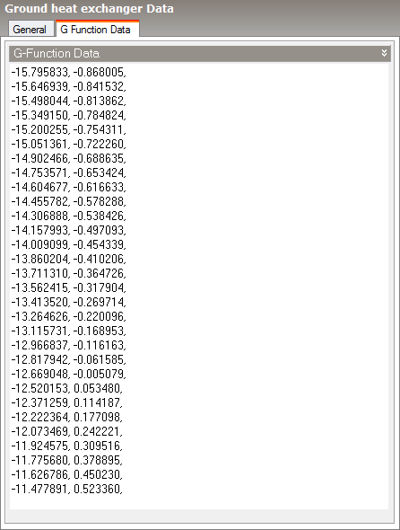
The borehole response is defined by a non-dimensional ‘G-function’ and the second tab includes a large text box with a list of G-function data pairs. The list is specified as a series of data points giving values of non-dimensional time vs G-function value (LNTTS1, GFUNC1), (LNTTS2, GFUNC2), (LNTTS3, GFUNC3) …….. (LNTTSn, GFUNCn)..
This numeric field contains the natural log of time/steady state time: ln(T/Ts).
This numeric field contains the G-function value of the corresponding LNTTS.
Example data:
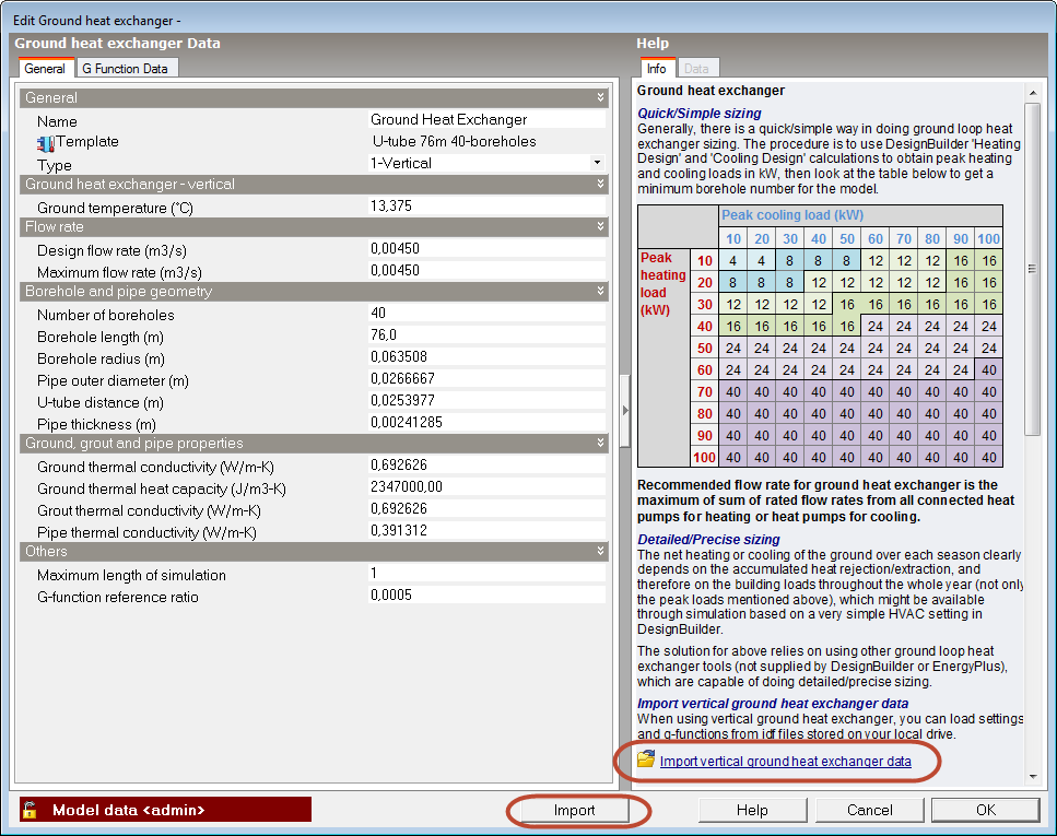
DesignBuilder provides a quick, approximate way to size vertical ground loop heat exchangers assuming typical borehole layouts and ground properties. The procedure is to use DesignBuilder Heating design and Cooling design calculations to obtain peak heating and cooling loads in kW, then use the table below to look up the minimum number of boreholes for the model.
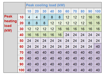
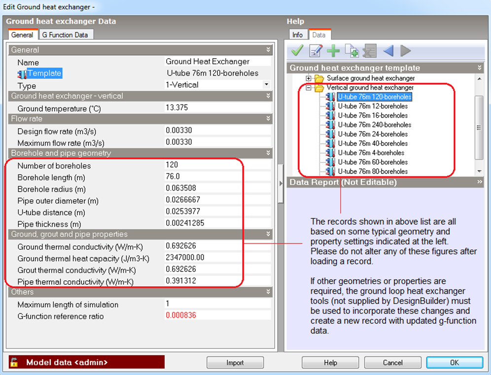
Then load the "U-Tube 76m xx-boreholes" vertical ground heat exchanger template with the corresponding number of boreholes from the template library. These templates include parameters pre-calculated based on a typical rectangular geometry and property settings (see left red-box in the figure below). Each includes a corresponding set of g-function data. For very different a bolehole layouts or when any of the ground or other parameter deviates significantly from these typical settings then you should use the Detailed design sizing method described below.
The net heating or cooling capacity of the ground over each season depends on the accumulated heat rejection/extraction, and therefore on the building loads throughout the whole year (not only the peak loads mentioned above), which might be available through simulation perhaps based on a simple HVAC setting in DesignBuilder.
Ground loop heat exchanger tools such as GLHEPRO and GLD (which are not supplied by DesignBuilder or EnergyPlus) are able to carry out a more detailed and accurate sizing calculation taking into account specific borehole layouts and ground properties. These tools can export calculated G-function data in the form of IDF files which can be loaded to the DesignBuilder Ground Heat Exchanger dialog as described below.
Data from a previously configured and sized vertical ground loop heat exchanger can be loaded by clicking on the Import button at the bottom of the dialog or the Import vertical ground heat exchanger data link from info panel (see figure below).
The corresponding g-function data will be loaded along with the rest of the data required on the dialog and can be viewed on the G Function Data tab.