Openings tab in model data under External Glazing and Internal Glazing headers
You can use settings such as Window to wall % (WWR) and Window height, Window spacing and Sill height to easily change the amount of glazing and its layout on the walls. The way this data is used for each façade type is described below.
There are a number of standard façade types:
Often referred to as the Window to Wall Ratio (WWR) this setting can be used to change the amount of glazing for all openings at or below the current level in the building hierarchy. For example changing the WWR at building level changes the size of all windows in the model not overridden by other settings lower in the hierarchy.
When using the 2-Outer volume Zone geometry and surface areas option (typically one of the "External measurements " convention templates) it is important to understand that the reference surface area used when calculating the window area from the % value supplied is based on the Window to wall ratio method which is accessed from the Constructions tab under the Geometry Areas and Volumesheader.
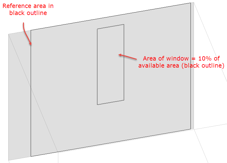
The image below illustrates a wall in a model using the "External measurements" geometry convention template where a window has been created using the 3-Preferred height façade option with a 10% glazing ratio. You can see the black outline showing the available area where the window could possibly be sited. Areas outside this outline to the left and right are taken up by corners with adjacent walls. The % glazing calculation uses the black outline area as the reference area. In an extreme case where 100% glazing is specified the whole of this area would be filled with window, but of course the sides of the surface where there is a corner with an adjacent surface cannot contain a window and so do not take part in the calculation - even though they will form part of the surface used in the simulation.
Tip: If you need to ensure that the % window areas used in the simulation exactly match the % you define here then you should consider using the "Simple" Geometry convention template which ensures that 100% of all surfaces are available for containing windows by using zero surface thickness for all surfaces.
The width of the windows including any frame (in m or ft).
The height of the windows including any frame (in m or ft).
The spacing between the each window on the façade (in m or ft). The window spacing is the centre to centre spacing between windows, not the gap between windows.
This is the height of the base of the window from the base of the block (in m or ft).
Note 1: You can control the makeup of the building façades in greater detail by drawing individual windows at the surface level or by copying previously drawn windows at building level. In either of these cases glazing, vent and door façade layout model data is ignored.
Note 2: Flat roofs do not have default glazing set up using Roof glazing layout model data. To create openings on a flat roof you should go to the surface level and add them there.
Note 3: When the surface is non-rectangular, even with the 2 façade type options that prioritise Window to wall % (3-Preferred height and 1-Continuous horizontal), the Window to wall % will not be perfectly maintained. For these surfaces, DesignBuilder calculates a rectangle that can accept the windows and starts from one end of the rectangle adding windows using the Window spacing data until no more fit into the rectangle. This results in an approximately correct looking façade but only prioritises Window to wall % in the rectangle, not accounting for the areas outside the bounding rectangle. For relatively large values of Window spacing on non-rectangular surfaces, no glazing may be generated. For example you may find that gable window surfaces have no default windows generated and it is often easiest to draw a window in this case.
Reveal surfaces are associated with the setback of the glazing from the outside and/or inside surface of the parent wall. If the depth and solar absorptance of these surfaces are specified, the program will calculate the reflection of beam solar radiation from these surfaces. The program also calculates the shadowing (onto the window) of beam and diffuse solar radiation by outside reveal surfaces.
The following fields specify the properties of the window reveal surfaces (reveals occur when the window is not in the same plane as the base surface). From this information and from the geometry of the window and the sun position, the program calculates beam solar radiation absorbed and reflected by the top, bottom, right and left sides of outside and inside window reveal surfaces. In doing this calculation, the shadowing on a reveal surface by other reveal surfaces is determined using the orientation of the reveal surfaces and the sun position.
It is assumed that:
The schematics below show how DesignBuilder reveal data is used to describe real glazing systems.
Although it is possible for inside reveal depth to be calculated from the outside reveal depth and the wall thickness, DesignBuilder allows both Inside and Outside reveal depths to be defined giving greater flexibility for situations where it is not possible to enter the wall thickness as accurately as one might like. For example the wall thickness may be entered as zero for simplified modelling. In such cases having direct control over the reveal depth data is an advantage.
The outside reveal depth gives the extent to which the glazing is offset into the wall. As shown in the above diagram it is the distance from the exterior surface of the wall to the glazing outer surface (in m or ft).
Note: The outside reveal depth is used in EnergyPlus, Visualisations and Daylighting calculations.
Note: EnergyPlus models outside reveals through the co-ordinates of the window, which are offset into the zone so the window and the base surface don't lie on the same plane. DesignBuilder provides window co-ordinates to EnergyPlus in this way and there is no specific data item in the IDF data to define it.
The inside reveal depth is the distance (in m or ft) from the innermost surface of the window to the interior wall surface as shown in the diagram above.
The inside sill depth is the distance (in m or ft) from the innermost surface of the window to the innermost end of the sill as shown in the diagram above.
The FenestrationSurface:Detailed window data written to the EnergyPlus IDF input file will usually have a smaller area compared with the gross window area defined in DesignBuilder. EnergyPlus window sizes and positions are defined for the glazing area and the frame is extended from the window position to the parent wall/roof surface. DesignBuilder therefore accounts for the frame which is included in the window area defined in DesignBuilder but excluded from the EnergyPlus IDF window area. In cases where the frame option is switched off in DesignBuilder the frame area in the IDF data will exactly match the area set in DesignBuilder.
See also: Glazing Assemblies