HVAC tab in model data under Mechanical Ventilation header
In Compact Unitary HVAC systems the supply fan has two different possible operating modes. The choices for this field are:
For most commercial buildings, continuous fan operation will continue to supply outside air to the zones as typically required by code. For continuous fan operation, the 'System Availability Schedule' (see above) is the supply fan operating schedule. For systems where the supply fan only runs when either cooling or heating needs to be supplied to the zone such as for many residential systems, cycling should be specified.
When using Simple HVAC, enter the type of fan. Select from:
Note that in Simple HVAC the Auxiliary energy data accounts for all fan, pump and other electrical energy use.
Enter the pressure rise at full flow and standard conditions. Standard conditions are considered 20C at sea level, 101325 Pa.
You can calculate the approximate fan pressure rise from Specific Fan Power (SFP) data using:
Delta P = 1000 * SFP * Fan total efficiency
Where SFP is fan power per flow rate in W/l/s.
Typical values for various system types are shown in the table below.
|
System Type |
Specific Fan Power (Watts/litre/second) |
|
Central mechanical ventilation including heating, cooling and heat recovery |
2.5 |
|
Central mechanical ventilation including heating and cooling |
2.0 |
|
All other systems |
1.8 |
|
Local ventilation units within the local area, such as window/wall/roof units, serving one room/area |
0.5 |
|
Local ventilation units remote from the local area, such as ceiling void or roof mounted units, serving one room/area |
1.2 |
|
Fan coil units (rating weighted average) |
0.8 |
Source ESTA: http://www.esta.org.uk/
Enter the product of the fan motor and impeller efficiency of the supply fan. This is the ratio of the power delivered to the air to the electrical input power at maximum flow expressed as a percentage. The motor efficiency is the power delivered to the shaft divided by the electrical power input to the motor. The fan efficiency is power delivered to the air divided by the shaft power. The power delivered to the fluid is the mass flow rate of the air multiplied by the pressure rise divided by the air density. Must be greater than 0 and less than or equal to 100.
Enter the percentage of the motor heat that is added to the air stream. A value of 0 means that the motor is completely outside the air stream. A value of 100 means that all of the motor heat will go into the air stream and act to cause a temperature rise. Must be between 0 and 100.
Enter the supply fan placement type. There are two choices:
The default is 1-Draw through.
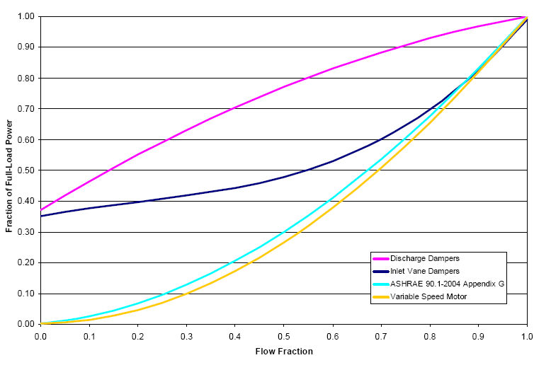
Select the set of generic pre-defined coefficients to use for the supply fan part-load power consumption. Choices are:
The resulting power curves are shown in the graph below. The ASHRAE 90.1-2004 Appendix G coefficients are from TABLE G3.1.3.15, Method 2. The other sets of coefficients are from the EnergyPlus Input Output Reference, Fan Coefficient Values table.