![]()
Blocks can be cut (i.e. divided into 2) using the Divide Block Tool. To cut or divide a block first go to the building level, select the block that you want to modify and click on the Divide block toolbar icon. Blocks are divided using a plane which can be defined using one of 2 methods:
The Draw plane cutting method involves drawing two lines which define the plane. For example to cut a pitched roof to fit flush with a rotunda:
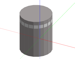
Because the geometry is fairly complicated, it's advisable to use an outline block to generate the intermediate geometry and then convert the block to a building block after the editing process is complete. So, from the building level, click on the Add new block tool, select 2-Outline block as the block type, set the perimeter shape to 1-Polygon and the Height to the same height as the rotunda, then draw a conventional vertical extrusion to fit flush to the rotunda. In order to trace round the base of the rotunda, it's probably easier to set the view rotation to 'Plan', click on to the ground plane and press SHIFT to lock the plane before placing the first perimeter point:
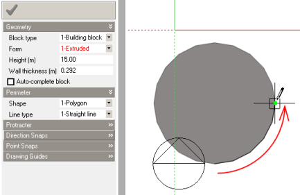
When tracing around a perimeter by snapping from end-point to end-point, it can be helpful to switch off the direction snaps and the drawing guides to prevent them from interfering with the point snaps. Completing the perimeter:
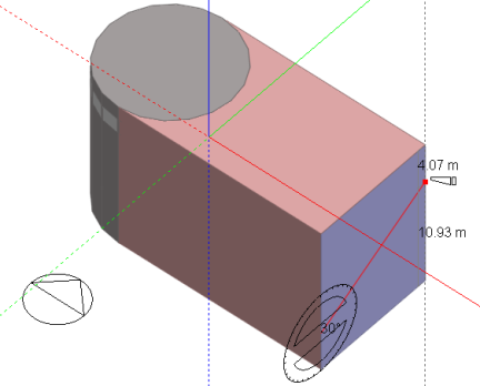
Click on the outline block to select it and then click on the 'Divide block' tool and make sure that the 'Cutting method' is set to 1-Draw plane in the Drawing Options data panel. Switch the protractor on and move the cursor over the end face of the selected block, the surface will highlight to indicate that it's become the active drawing plane. Press the SHIFT key to lock the drawing plane and then locate the cursor 4m from the base of the block using edge snap:
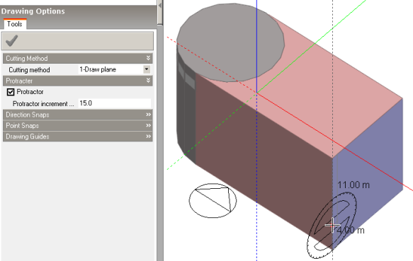
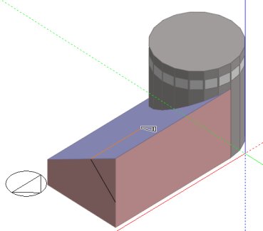
Click to place the beginning of the first cutting plane line, then place the end of the line to intersect the face edge with a pitch angle of 30°:
Orbit to make the back face of the block visible. Move the mouse cursor over the back face and when it highlights, press the SHIFT key to lock the plane. Place the second cutting plane line to snap to the local X-axis of the back face:
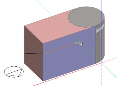
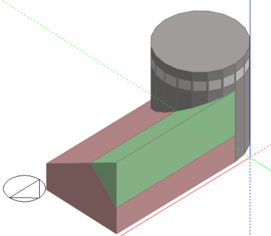
Click to complete the cutting plane. The blocks that will be produced by the cut are displayed in red and green, depending on which side of the cutting plane they lie. At this point, you can choose to cancel the cut by pressing the ESC key or selecting 'Cancel Cut' from the right-click menu.
Click again to complete the cut and then select and delete the block that isn't needed:
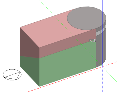
Go through a similar process to create the other pitch. You may need to switch off the drawing guides and mid-point snap to prevent them from interfering with the protractor and edge snap:
Click to create the cutting plane:
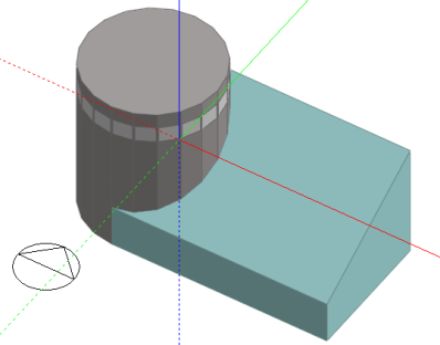
Click again to make the final cut and then select and delete the block that isn't part of the finished structure:
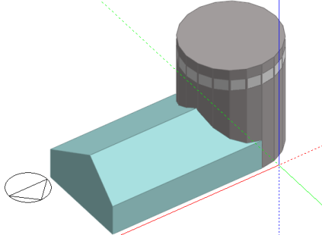
The outline block can then be selected and converted to a building block:
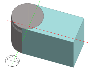
The Select plane method of cutting a block uses an existing plane to define the cutting plane. It can be demonstrated by modelling a roof offshoot:
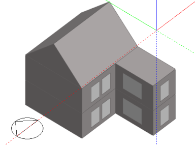
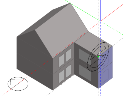
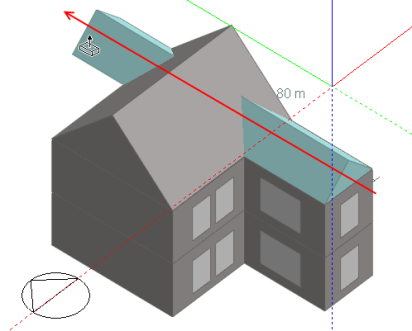
Click on the 'Add new block' tool, select 2-Outline block as the block type and set the perimeter shape to 1-Polygon. Switch the protractor on and move the mouse cursor to the back face of the offshoot. When the cursor is over the back face, press the SHIFT key to lock the drawing plane and snap the protractor to the upper edge end-point:
Draw the first perimeter line at a 45° pitch and move the cursor to intersect with the back face upper edge mid-point drawing guide and click to set the end-point:
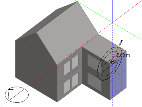
Move the cursor to snap to the other end-point of the back face upper edge and then complete the perimeter:
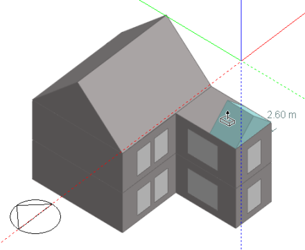
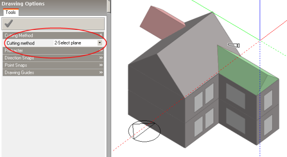
Now drag the outline block face through the main roof block:
Select the offshoot outline block and click on the ‘Cut block along plane’ tool, making sure that the ‘Cutting method’ on the ‘Drawing options’ data panel is set to 'Select plane’ and click on the forward facing plane of the main roof block to create a cut in the offshoot block in the plane of the roof:
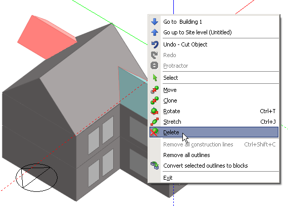
Click again to finish the cut and then select the section of the offshoot roof block that is not required and delete it:
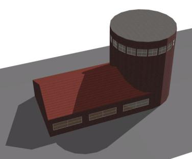
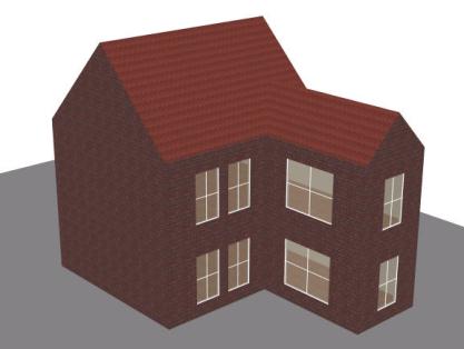
Select the roof offshoot block and click on the 'Convert selected outline blocks to building blocks' tool to complete the process:
In some circumstances, resulting blocks may not be able to be converted to building blocks due to geometrical limitations. In this case, the block will be displayed in a sepia colour to indicate that it cannot be converted.