![]()
To add or create a new block, first go to the building level (if you are not already there) and click on the Add new block tool. If you've just created a new building, the Add new block tool is automatically activated. A block is created by drawing the base perimeter of the block using one of the perimeter shapes such as a polygon. The dimensions of the block are those measured from the outside, the height of the block is the floor-floor height.
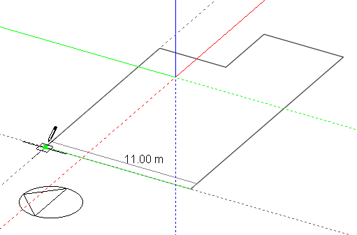
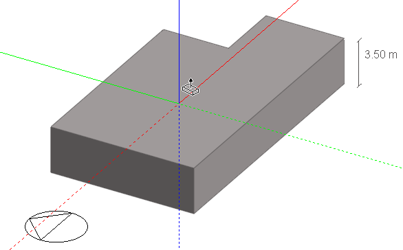
Please refer to perimeter shapes for details of drawing perimeters. After drawing a perimeter, a block will be automatically extruded by the Height entry in the ‘Drawing options’ settings or if the Auto-complete block setting is switched off, the perimeter can be dragged to form the extrusion. To help in setting the correct extrusion height, the increment snap setting can be used which enables the drag movement to jump by any defined increment. Alternatively, you can simply type in an extrusion height and press the enter key:
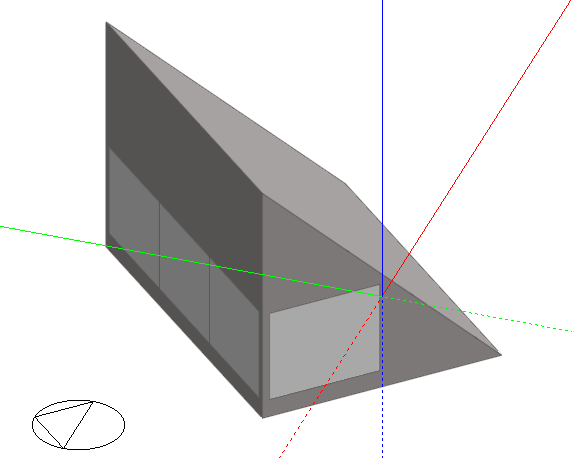
When a block has been placed, additional blocks can be drawn onto any surface of the block to form more complex aggregate blocks. As you move the mouse cursor across the faces of an existing block, each face will change colour from grey to blue to indicate the active drawing plane. You can lock the active drawing plane by pressing the SHIFT key, which allows you to move the cursor off the current face while keeping the plane active. You can also lock the active drawing plane to the ground plane by moving the cursor over the background area and pressing the SHIFT key, this is particularly helpful in avoiding the selection of the wrong plane when drawing a vertically extruded block adjacent to an existing block. Once you’ve clicked the first data point into the active drawing plane, it becomes locked regardless of whether or not the SHIFT key is pressed until the perimeter has been completed or the tool is cancelled. In the example below the vertical plane shown in blue has been selected, the shape of the block will be drawn in this plane and the volume created by extruding normal to it.
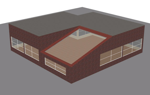
When a block is added to the surface of another block, a geometric link is automatically created between the two blocks:
A hole can be added to the mating surface of this link (the inter-block partition) in order to form one contiguous space:
Note: the Merge zones connected by holes Model option must be set if you wish the two zones in the 2 blocks to be treated as one zone in the thermal calculations.
As already illustrated, a block perimeter can be drawn on the ground plane or onto the surface of an existing block in which case the perimeter is extruded normal to the surface on which it is drawn.
If the perimeter includes indents in such a way that the requested wall thickness is physically impossible and the wall thickness cannot be accommodated then DesignBuilder will still allow the block to be created but the wall thickness is reset to a small value (typically 0.025m). See the Wall thickness topic for more on this.
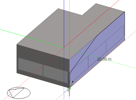
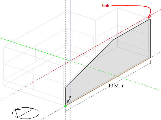
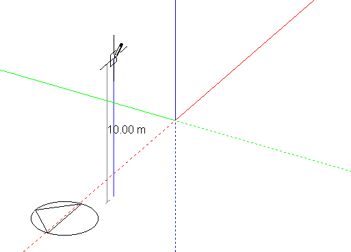
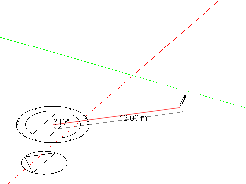
To create horizontal extrusions from a vertical plane, the first perimeter line can be aligned with the Z-axis using the axis snap:
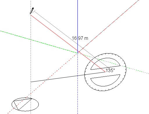
The protractor can be used to place the second line in order to accurately define the orientation of the plane relative to the base or ground plane:
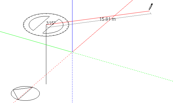
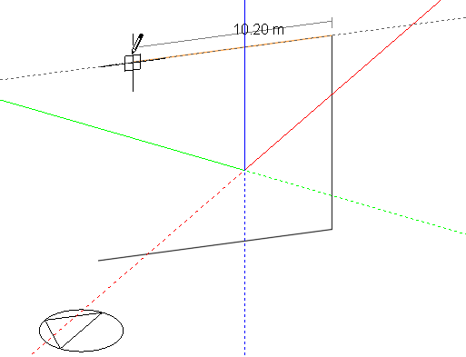
Alternatively, the orientation of the plane can be defined using the first line:
Snapping the second line to the Z-axis then forms the horizontal extrusion:
Once a vertical plane has been defined it will be ‘remembered’ until the ‘Add new block’ command is cancelled, so the perimeter can be ‘unwound’ using the ESC key or the right-click menu ‘Undo last point’ entry and any perimeter shape drawn into the stored plane:
After drawing the last perimeter line to connect to the perimeter start point, the perimeter can then be dragged to create a horizontally extruded block: