DXF and other bitmap-type drawing data formats can be imported in the form of 2-D floor plan layouts. These can be used to trace block perimeters and partitions as a fast way to enter the model geometry. A typical process might go like this:
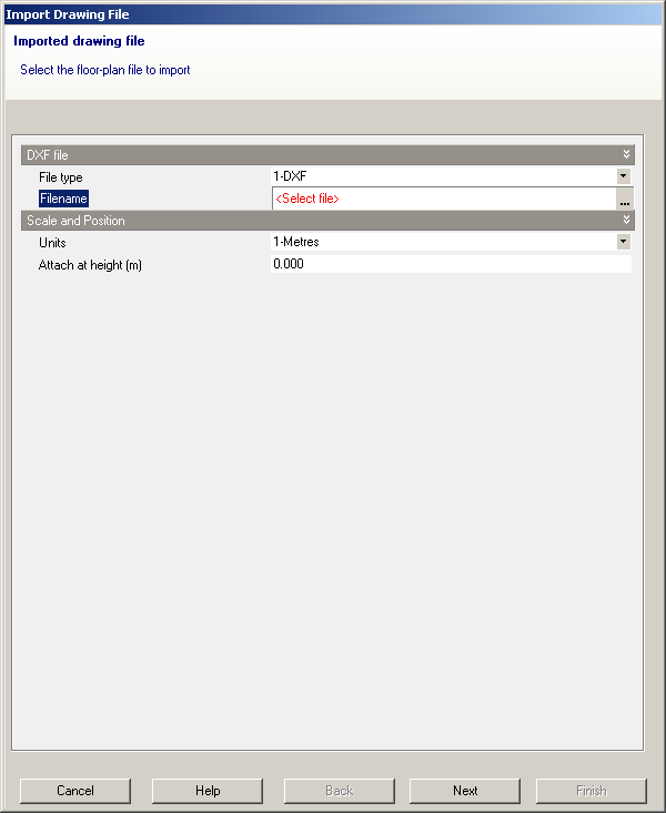
You can import 2-D DXF floor plan files created in AutoCAD or other CAD programs or the other bitmap-based drawing formats listed below. To start the process click on the Files > Import > Import 2-D drawing file menu command. This starts a the Import Drawing File Wizard (below).
First select the File type to import. You can select from:
When you have selected the file type then select the file by clicking into the 'Filename' control. Click on the ellipsis button to open the file browser dialogue box.
If you selected a DXF file you should then set the units used in the DXF file from the 'Units' drop list and set the attachment height at which the 2-D DXF data will be attached. The DXF data can be moved around the model once it is imported, so you do not need to know the exact attachment height - you can import the DXF data at zero height and move it to the correct location using the Move command. Click on the 'Next' button to set up layer visibility:
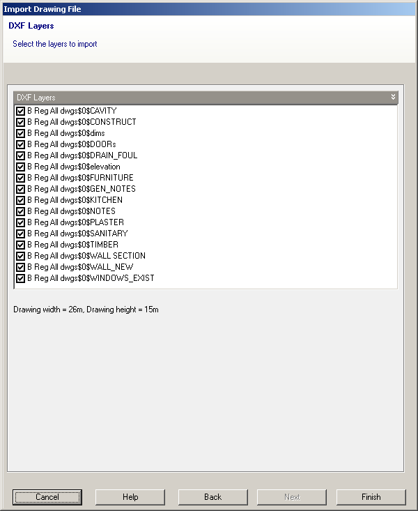
You can use these controls to switch off unnecessary layers in the DXF data. As you check/uncheck the checkboxes you will see the effect of the change in the Edit view under the Wizard. Click on the 'Finish' button to import the data:
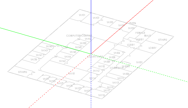
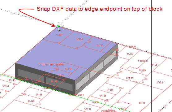
At the building level, you can select, move and delete DXF data. When you select DXF data, you may need to zoom in to make the selection. You can move DXF file in 3-D and snap the data to the edges of blocks:
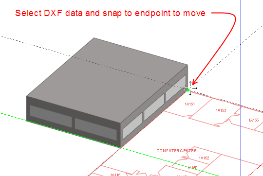
Move the DXF data on top of the existing block and snap to an edge end-point:
When you have imported the DXF data you can use the Measure tool to check that the dimensions are correct.
Import DXF floor plans for other stories if necessary. Note that only one set of DXF data can be imported at a time. Once the CAD data has been imported into the model, the source DXF file is no longer needed by DesignBuilder and can be moved or deleted.
The DXF data must be selected to allow these operations:
Move - move the DXF data
Delete - delete the DXF data (not the source file itself).
Also these 2 menu commands are available from the Edit menu when DXF data is loaded:
When the command is started click twice to define the end points of a line in the direction of the X-axis on the imported DXF data. After the operation the DXF data is rotated to align with the DesignBuilder X-axis. Normally DXF data will already be orientated to the grid and this command is not required.
This command allows you to scale the DXF data to be larger or smaller. This may be necessary if the scale of the DXF data was unknown at the import stage. When the command is started click twice to define the end points of a reference line on the DXF data of known length (e.g. a dimension arrow or known length on a building wall). Then either move the cursor to define the new length of the reference line and click again or type in the dimension of the reference line. So a typical sequence might be:
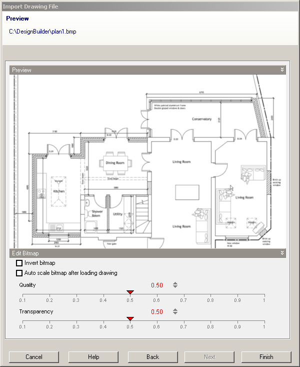
When the file type is one of the bitmap based formats (PDF, BMP, JPG, PNG, GIF, TIFF collectively referred to here as 'bitmap' ) the next page of the Wizard provides a preview of the drawing and some options.
Check this option if you wish the colours in the bitmap to be inverted. For example if the picture is white on a black background then it will generally be best to invert these for use in DesignBuilder.
If you wish the 'scale bitmap' command to be automatically started when the Import Drawing File Wizard in closed then check this option.
By reducing the number of pixels in the bitmap it is possible to significantly reduce the size of the imported drawing data and hence speed subsequent drawing 'scale' and 'rotate'operations. Quality setting of 0.5 gives a good trade-off between image size and readability but if the drawing file is particularly large you may decide to reduce the quality and vice-versa.
You can control the transparency of the drawing data from 0 to 1.
Bitmap-based files may be used for:
Note: bitmap drawings do not allow end-point snap like DXF but can be an equally effective option for rapid geometry entry in DesignBuilder.
The bitmap data must be selected to allow these operations:
Move - move the bitmap data.
Delete - delete the bitmap data.
Also these 2 commands are available from the Edit menu when bitmap data is loaded:
Sometimes scanned bitmap files are not exactly aligned to the X-axis and you can use this command to re-orientate the drawing. When the command is started click twice to define the end points of a line in the direction of the X-axis on the imported bitmap data. After the operation the bitmap data is rotated to align with the DesignBuilder X-axis.
This command allows you to scale the bitmap data to be larger or smaller. This will usually be necessary for bitmap drawing formats as the scale is not defined at the import stage. When the command is started click twice to define the end points of a reference line on the bitmap data of known length (e.g. a dimension arrow or known length on a building wall). Then either move the cursor to define the new length of the reference line and click again or type in the dimension of the reference line. So a typical sequence might be:
You can also use the imported floor plan data to draw internal partitions. To do this go to block level and draw partitions by tracing over using the floor plan partition data. You should take care to connect partitions to the external perimeters. A common mistake is to snap partitions to DXF data lying very close to the external perimeter but not close enough to create a connection with the external perimeter. It is recommended that you switch of DXF snap in the Drawing options panel when drawing partitions at block level to avoid this problem. Be sure to switch it back on again when you have finished drawing partitions.
